Nissan Murano Z50 (2003 year). Manual - part 19
INTEGRATED DISPLAY SYSTEM
AV-97
C
D
E
F
G
H
I
J
L
M
A
B
AV
Revision; 2004 April
2003 Murano
Terminals and Reference Value for Display Unit
AKS004XW
Terminal
(Wire color)
Item
Signal
input/
output
Condition
Reference value
Example of
symptom
+
–
Ignition
switch
Operation
1 (Y)
Ground
Battery power
supply
Input
OFF
-
Battery voltage
System does not
work properly.
2 (P/B)
Ground
ACC power
supply
Input
ACC
-
Battery voltage
System does not
work properly.
3 (G)
Ground
Ignition signal
Input
ON
-
Battery voltage
A/C operation is
not possible.
Vehicle informa-
tion setting is not
possible.
4 (R/L)
Ground
Illumination
signal
Input
OFF
Lighting switch is
ON (position 1).
Approx. 12V
Screen does not
switch between
daytime mode
and night-time
mode.
Turn lighting switch
OFF.
Approx. 0V
6 (B)
Ground
Ground
-
ON
-
Approx. 0V
-
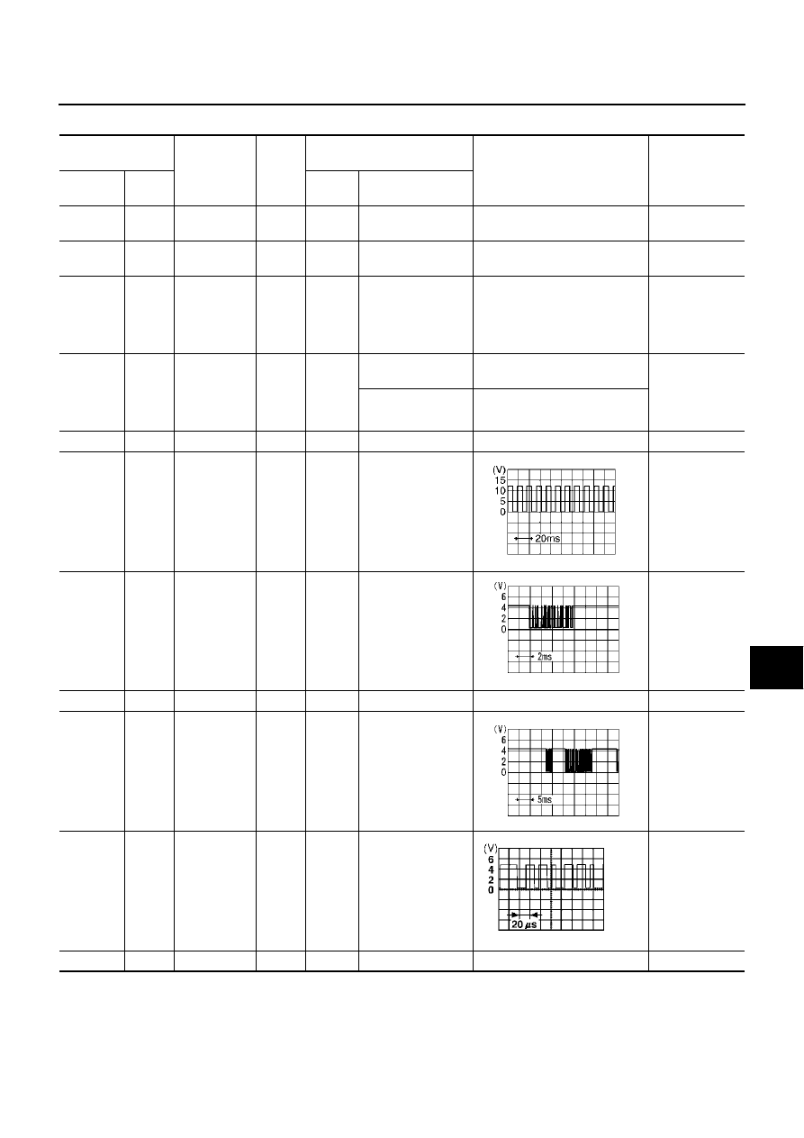
7 (V/W)
Ground
Vehicle
speed signal
(8-pulse)
Input
ON
When vehicle speed
is approx. 40 km/h
(25 MPH)
Drive computer
item is not dis-
played correctly.
8 (R/G)
Ground
Audio TX
Output
ON
Operate audio vol-
ume.
Audio does not
operate prop-
erly.
9
Ground
Shield
-
ON
-
Approx. 0V
-
10 (R/Y)
Ground
Audio RX
Input
ON
Operate audio vol-
ume.
Audio does not
operate prop-
erly.
11 (L/G)
Ground
Communica-
tion signal (+)
Input/
output
ON
-
System does not
work properly.
12
Ground
Shield
-
ON
-
Approx. 0V
-
PKIA1935E
SKIA4402E
SKIA4403E
SKIA0175E