Nissan Murano Z51 (2008 year). Manual - part 414
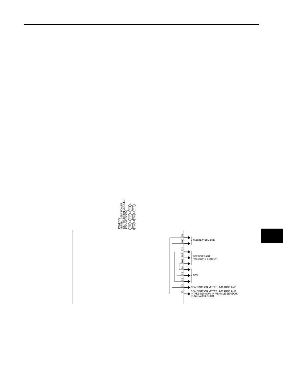
IPDM E/R (INTELLIGENT POWER DISTRIBUTION MODULE ENGINE ROOM)
WW-107
< ECU DIAGNOSIS >
C
D
E
F
G
H
I
J
K
M
A
B
WW
N
O
P
JCMWM3174GB
Revision: 2008 October
2009 Murano
|
|
|
IPDM E/R (INTELLIGENT POWER DISTRIBUTION MODULE ENGINE ROOM) WW-107 < ECU DIAGNOSIS > C D E F G H I J K M A B WW N O P JCMWM3174GB Revision: 2008 October 2009 Murano |