Nissan Murano Z51 (2008 year). Manual - part 415
FRONT WASHER NOZZLE AND TUBE
WW-123
< ON-VEHICLE REPAIR >
C
D
E
F
G
H
I
J
K
M
A
B
WW
N
O
P
FRONT WASHER NOZZLE AND TUBE
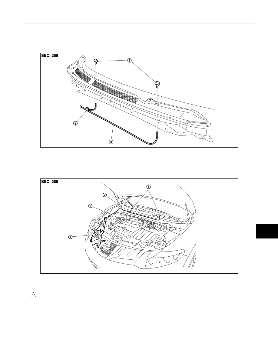
Exploded View
INFOID:0000000003307671
Hydraulic Layout
INFOID:0000000003307672
Removal and Installation
INFOID:0000000003307673
REMOVAL
1.
Remove cowl top cover. Refer to
2.
Disconnect front washer tube from front washer nozzle.
1.
Front washer nozzle
2.
Check valve
3.
Front washer tube
JPLIA0869ZZ
1.
Front washer nozzle
2.
Check valve
3.
Front washer tube
4.
Washer tank
: Clip
JPLIA0870ZZ
Revision: 2008 October
2009 Murano