Nissan Murano Z51 (2008 year). Manual - part 408


  Index      Manuals     Nissan Murano Z51 (2008 year) - Service and Repair Manual


Search            copyright infringement  


Content      ..     406      407      408      409     ..


Nissan Murano Z51 (2008 year). Manual - part 408


FRONT WIPER AND WASHER SYSTEM

WW-11

< FUNCTION DIAGNOSIS >

C

D

E

F

G

H

I

J

K

M

A

B

WW

N

O

P

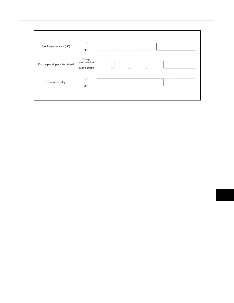
• When the front wiper request signal is stopped, IPDM E/R turns ON the front wiper relay until the front wiper

motor returns to the stop position.

NOTE:
• BCM stops the transmitting of the front wiper request signal when the ignition switch is OFF.
• IPDM E/R turns the front wiper relay OFF when the ignition switch is OFF.

FRONT WIPER OPERATION LINKED WITH WASHER

• BCM transmits the front wiper request signal (LO) to IPDM E/R with CAN communication according to the

washer linked operating condition of the front wiper.

• BCM transmits the front wiper request signal (LO) so that the front wiper operates approximately 2 times

when the front washer switch OFF is detected.

Washer linked operating condition of front wiper

- Ignition switch ON
- Front washer switch ON (0.4 second or more)
• IPDM E/R turns ON the integrated front wiper relay according to the front wiper request signal (LO).
• The washer pump is grounded through the combination switch with the front washer switch ON.

FRONT WIPER FAIL-SAFE OPERATION

IPDM E/R performs the fail-safe function when the front wiper auto stop circuit is malfunctioning. Refer to

PCS-30, "Fail-safe"

.

JPLIA0410GB

Revision: 2008 October

2009 Murano

WW-12

< FUNCTION DIAGNOSIS >

FRONT WIPER AND WASHER SYSTEM

WITHOUT RAIN SENSOR : Component Parts Location

INFOID:0000000003514395

WITHOUT RAIN SENSOR : Component Description

INFOID:0000000003514396

1.

Combination switch

2.

Combination meter

3.

Washer pump

4.

Front wiper motor

5.

IPDM E/R

6.

BCM

A.

Radiator core support (RH)

B.

Cowl top, left side of engine room

C.

Engine room (left side)

D.

Behind combination meter

JPLIA0908ZZ

Part

Description

BCM

• Judges each switch status by the combination switch reading function.
• Requests (with CAN communication) the front wiper relay and the front wiper high relay ON to 

IPDM E/R.

IPDM E/R

• Controls the integrated relay according to the request (with CAN communication) from BCM.
• Performs the auto stop control of the front wiper.

Revision: 2008 October

2009 Murano

FRONT WIPER AND WASHER SYSTEM

WW-13

< FUNCTION DIAGNOSIS >

C

D

E

F

G

H

I

J

K

M

A

B

WW

N

O

P

Combination switch
(Wiper & washer switch)

Refer to 

BCS-9, "System Diagram"

.

Combination meter

Transmits the vehicle speed signal to BCM with CAN communication.

Part

Description

Revision: 2008 October

2009 Murano

WW-14

< FUNCTION DIAGNOSIS >

REAR WIPER AND WASHER SYSTEM

REAR WIPER AND WASHER SYSTEM

System Diagram

INFOID:0000000003307606

System Description

INFOID:0000000003307607

OUTLINE

The rear wiper is controlled by each function of BCM.

Control by BCM

• Combination switch reading function
• Rear wiper control function

REAR WIPER BASIC OPERATION

• BCM detects the combination switch condition by the combination switch reading function.
• BCM controls the rear wiper to start or stop.

REAR WIPER ON OPERATION

• BCM supplies power to the rear wiper motor according to the rear wiper ON operating condition.

Rear wiper ON operating condition

- Ignition switch ON
- Rear wiper switch ON

REAR WIPER INT OPERATION

• BCM supplies power to the rear wiper motor according to the INT operating condition.

Rear wiper INT operating condition

- Ignition switch ON
- Rear wiper switch INT
• BCM controls the rear wiper to operate once.
• BCM detects the rear wiper motor stopping position.
• BCM supplies power to the rear wiper motor after an intermittent from the stop of the rear wiper motor.

REAR WIPER AUTO STOP OPERATION

• BCM stops supplying power to the rear wiper motor when the rear wiper switch is turned OFF.

JPLIA1257GB

JPLIA1258GB

Revision: 2008 October

2009 Murano

REAR WIPER AND WASHER SYSTEM

WW-15

< FUNCTION DIAGNOSIS >

C

D

E

F

G

H

I

J

K

M

A

B

WW

N

O

P

• BCM reads a rear wiper stop position signal from the rear wiper motor to detect a rear wiper motor position.
• When the rear wiper motor is at other than the stopping position, BCM continues to supply power to the rear

wiper motor until it returns to the stopping position.

NOTE:
BCM stops supplying power to the rear wiper motor when the ignition switch is turned OFF.

REAR WIPER OPERATION LINKED WITH WASHER 

• BCM supplies power to the rear wiper motor according to the washer linked operating condition of rear

wiper. When the rear washer switch is turned OFF, BCM controls rear wiper to operate approximately 3
times.

Washer linked operating condition of rear wiper

- Ignition switch ON
- Rear washer switch ON (0.4 second or more)
• The washer pump is grounded through the combination switch with the rear washer switch ON.

REAR WIPER FAIL

SAFE OPERATION

BCM performs the fail-safe function when the rear wiper auto stop circuit is malfunctioning. Refer to 

BCS-87,

"Fail-safe"

.

JPLIA1259GB

Revision: 2008 October

2009 Murano

WW-16

< FUNCTION DIAGNOSIS >

REAR WIPER AND WASHER SYSTEM

Component Parts Location

INFOID:0000000003307608

Component Description

INFOID:0000000003307609

1.

Combination switch

2.

Washer pump

3.

BCM

4.

Rear wiper motor

A.

Radiator core support (RH)

B.

Behind combination meter

C.

Back door trim finisher lower inside

JPLIA0897ZZ

Part

Description

BCM

• Judges each switch status by the combination switch reading function.
• Supplies power to the rear wiper motor.
• Performs the auto stop control of the rear wiper.

Combination switch
(Wiper & washer switch)

Refer to 

BCS-9, "System Diagram"

.

Revision: 2008 October

2009 Murano

DIAGNOSIS SYSTEM (BCM)

WW-17

< FUNCTION DIAGNOSIS >

C

D

E

F

G

H

I

J

K

M

A

B

WW

N

O

P

DIAGNOSIS SYSTEM (BCM)

COMMON ITEM

COMMON ITEM : CONSULT-III Function (BCM - COMMON ITEM)

INFOID:0000000003691836

APPLICATION ITEM

CONSULT-III performs the following functions via CAN communication with BCM.

SYSTEM APPLICATION

BCM can perform the following functions for each system.
NOTE:
It can perform the diagnosis modes except the following for all sub system selection items.

×

: Applicable item

NOTE:

• *1: At models with Intelligent Key system this item is displayed, but is not used.

• *2: At models with rain sensor this mode is displayed, but is not used.

Diagnosis mode

Function Description

Work Support

Changes the setting for each system function.

Self Diagnostic Result

Displays the diagnosis results judged by BCM.

CAN Diag Support Monitor

Monitors the reception status of CAN communication viewed from BCM. Refer to CONSULT-III opera-
tion manual.

Data Monitor

The BCM input/output signals are displayed.

Active Test

The signals used to activate each device are forcibly supplied from BCM.

Ecu Identification

The BCM part number is displayed.

Configuration

• Read and save the vehicle specification.
• Write the vehicle specification when replacing BCM.

System

Sub system selection item

Diagnosis mode

Work Support

Data Monitor

Active Test

Door lock

DOOR LOCK

×

×

×

Rear window defogger

REAR DEFOGGER

×

×

Warning chime

BUZZER

×

×

Interior room lamp timer

INT LAMP

×

×

×

Remote keyless entry system

MULTI REMOTE ENT*

1

×

×

×

Exterior lamp

HEAD LAMP

×

×

×

Wiper and washer

WIPER

×

*

2

×

×

Turn signal and hazard warning lamps

FLASHER

×

×

×

AIR CONDITONER*

3

• Intelligent Key system
• Engine start system

INTELLIGENT KEY

×

×

×

Combination switch

COMB SW

×

Body control system

BCM

×

NVIS - NATS

IMMU

×

×

Interior room lamp battery saver

BATTERY SAVER

×

×

×

Back door opener system

TRUNK

×

×

Vehicle security system

THEFT ALM

×

×

×

RAP system

RETAINED PWR

×

Signal buffer system

SIGNAL BUFFER

×

×

TPMS

TPMS (AIR PRESSURE MONITOR)

×

×

×

Revision: 2008 October

2009 Murano

WW-18

< FUNCTION DIAGNOSIS >

DIAGNOSIS SYSTEM (BCM)

• *3: This item is displayed, but is not used. 

FREEZE FRAME DATA (FFD)

The BCM records the following vehicle condition at the time a particular DTC is detected, and displays on
CONSULT-III.

WIPER

WIPER : CONSULT-III Function (BCM - WIPER)

INFOID:0000000003307615

WORK SUPPORT

CONSULT screen item

Indication/Unit

Description

Vehicle Speed

km/h

Vehicle speed of the moment a particular DTC is detected

Odo/Trip Meter

km

Total mileage (Odometer value) of the moment a particular DTC is detected

Vehicle Condition

SLEEP>LOCK

Power position status of 
the moment a particular 
DTC is detected

While turning BCM status from low power consumption mode to 
normal mode (Power supply position is “LOCK”)

SLEEP>OFF

While turning BCM status from low power consumption mode to 
normal mode (Power supply position is “OFF”.)

LOCK>ACC

While turning power supply position from “LOCK” to “ACC”

ACC>ON

While turning power supply position from “ACC” to “IGN”

RUN>ACC

While turning power supply position from “RUN” to “ACC” (Vehicle 
is stopping and selector lever is except P position.)

CRANK>RUN

While turning power supply position from “CRANKING” to “RUN” 
(From cranking up the engine to run it)

RUN>URGENT

While turning power supply position from “RUN“ to “ACC” (Emer-
gency stop operation)

ACC>OFF

While turning power supply position from “ACC” to “OFF”

OFF>LOCK

While turning power supply position from “OFF” to “LOCK”

OFF>ACC

While turning power supply position from “OFF” to “ACC”

ON>CRANK

While turning power supply position from “IGN” to “CRANKING”

OFF>SLEEP

While turning BCM status from normal mode (Power supply posi-
tion is “OFF”.) to low power consumption mode

LOCK>SLEEP

While turning BCM status from normal mode (Power supply posi-
tion is “LOCK”.) to low power consumption mode

LOCK

Power supply position is “LOCK” (Ignition switch OFF with steer-
ing is locked.)

OFF

Power supply position is “OFF” (Ignition switch OFF with steering 
is unlocked.)

ACC

Power supply position is “ACC” (Ignition switch ACC)

ON

Power supply position is “IGN” (Ignition switch ON with engine 
stopped)

ENGINE RUN

Power supply position is “RUN” (Ignition switch ON with engine 
running)

CRANKING

Power supply position is “CRANKING” (At engine cranking)

IGN Counter

0 - 39

The number of times that ignition switch is turned ON after DTC is detected
• The number is 0 when a malfunction is detected now.
• The number increases like 1 

 2 

 3...38 

 39 after returning to the normal condition 

whenever ignition switch OFF 

 ON.

• The number is fixed to 39 until the self-diagnosis results are erased if it is over 39.

Revision: 2008 October

2009 Murano

DIAGNOSIS SYSTEM (BCM)

WW-19

< FUNCTION DIAGNOSIS >

C

D

E

F

G

H

I

J

K

M

A

B

WW

N

O

P

*:Factory setting

NOTE:
Work support item is not indicated when the vehicle with rain sensor.

DATA MONITOR

ACTIVE TEST

Service item

Setting item

Description

WIPER SPEED 
SETTING

On

With vehicle speed
(Front wiper intermittent time linked with the vehicle speed and wiper intermittent dial position)

Off*

Without vehicle speed
(Front wiper intermittent time linked with the wiper intermittent dial position)

Monitor Item

[Unit]

Description

PUSH SW
[Off/On]

The switch status input from push-button ignition switch.

VEHICLE SPEED 1
[km/h]

The value of the vehicle speed signal received from combination meter with CAN communication.

FR WIPER HI
[Off/On]

Each switch status that BCM judges from the combination switch reading function.

FR WIPER LOW
[Off/On]

FR WASHER SW
[Off/On]

FR WIPER INT
[Off/On]

FR WIPER STOP
[Off/On]

Front wiper motor (stop position) status received from IPDM E/R with CAN communication.

INT VOLUME
[1 

 7] 

Each switch status that BCM judges from the combination switch reading function.

RR WIPER ON
[Off/On]

Each switch status that BCM judges from the combination switch reading function.

RR WIPER INT
[Off/On]

RR WASHER SW
[Off/On]

RR WIPER STOP
[Off/On]

Rear wiper motor (stop position) status input from the rear wiper motor.

Test item

Operation

Description

FR WIPER

Hi

Transmits the front wiper request signal (HI) to IPDM E/R with CAN communication to operate 
the front wiper HI operation.

Lo

Transmits the front wiper request signal (LO) to IPDM E/R with CAN communication to operate 
the front wiper LO operation.

INT

Transmits the front wiper request signal (INT) to IPDM E/R with CAN communication to operate 
the front wiper INT operation.

Off

Stops transmitting the front wiper request signal to stop the front wiper operation.

RR WIPER

On

Outputs the voltage to operate the rear wiper motor.

Off

Stops the voltage to stop.

Revision: 2008 October

2009 Murano

WW-20

< FUNCTION DIAGNOSIS >

DIAGNOSIS SYSTEM (IPDM E/R)

DIAGNOSIS SYSTEM (IPDM E/R)

Diagnosis Description

INFOID:0000000003733521

AUTO ACTIVE TEST

Description

In auto active test mode, the IPDM E/R sends a drive signal to the following systems to check their operation.
• Oil pressure warning lamp
• Front wiper (LO, HI)
• Parking lamps
• License plate lamps
• Side maker lamps
• Tail lamps
• Front fog lamps
• Headlamps (LO, HI)
• A/C compressor (magnet clutch)
• Cooling fan

Operation Procedure

1.

Close the hood and lift the wiper arms from the windshield. (Prevent windshield damage due to wiper
operation)
NOTE:
When auto active test is performed with hood opened, sprinkle water on windshield beforehand.

2.

Turn the ignition switch OFF.

3.

Turn the ignition switch ON, and within 20 seconds, press the front door switch (driver side) 10 times.
Then turn the ignition switch OFF.

CAUTION:

Close passenger door.

4.

Turn the ignition switch ON within 10 seconds. After that the horn sounds once and the auto active test
starts.

5.

The oil pressure warning lamp starts blinking when the auto active test starts.

6.

After a series of the following operations is repeated 3 times, auto active test is completed.

NOTE:
When auto active test mode has to be cancelled halfway through test, turn the ignition switch OFF.

CAUTION:

• If auto active test mode cannot be actuated, check door switch system. Refer to 

DLK-411,

"Component Function Check"

.

• Do not start the engine.

Inspection in Auto Active Test Mode

When auto active test mode is actuated, the following 6 steps are repeated 3 times.

Operation 
sequence

Inspection location

Operation

1

Oil pressure warning lamp

Blinks continuously during operation of auto active test 

2

Front wiper

LO for 5 seconds 

 HI for 5 seconds

3

• Parking lamps
• License plate lamps
• Side maker lamps
• Tail  lamps
• Front  fog  lamps

10 seconds

4

Headlamps

LO 

 HI 5 times

5

A/C  compressor  (magnet clutch)

ON 

 OFF 5 times

6

Cooling fan

LO for 5 seconds 

 MID for 3 seconds 

 HI for 2 seconds

Revision: 2008 October

2009 Murano

DIAGNOSIS SYSTEM (IPDM E/R)

WW-21

< FUNCTION DIAGNOSIS >

C

D

E

F

G

H

I

J

K

M

A

B

WW

N

O

P

Concept of auto active test

• IPDM E/R starts the auto active test with the door switch signals transmitted by BCM via CAN communica-

tion. Therefore, the CAN communication line between IPDM E/R and BCM is considered normal if the auto
active test starts successfully.

• The auto active test facilitates troubleshooting if any systems controlled by IPDM E/R cannot be operated.

Diagnosis chart in auto active test mode

JPMIA0909GB

Symptom

Inspection contents

Possible cause

Any of the following components do not operate

• Parking  lamps
• License plate lamps
• Side maker lamps
• Tail  lamps
• Front fog lamps
• Headlamp (HI, LO)
• Front wiper (HI, LO)

Perform auto active test.
Does the applicable system 
operate?

YES

BCM signal input circuit

NO

• Lamp or motor
• Lamp or motor ground cir-

cuit

• Harness or connector be-

tween IPDM E/R and appli-
cable system

• IPDM E/R

A/C compressor does not operate

Perform auto active test.
Does the magnet clutch oper-
ate?

YES

• A/C amp. signal input circuit
• CAN communication signal 

between A/C amp. and 
ECM

• CAN communication signal 

between ECM and IPDM E/
R

NO

• Magnet clutch
• Harness or connector be-

tween IPDM E/R and mag-
net clutch

• IPDM E/R

Oil pressure warning lamp does not operate

Perform auto active test.
Does the oil pressure warning 
lamp blink?

YES

• Harness or connector be-

tween IPDM E/R and oil 
pressure switch

• Oil pressure switch
• IPDM E/R

NO

• CAN communication signal 

between IPDM E/R and 
BCM

• CAN communication signal 

between BCM and combi-
nation meter

• Combination meter

Revision: 2008 October

2009 Murano

WW-22

< FUNCTION DIAGNOSIS >

DIAGNOSIS SYSTEM (IPDM E/R)

CONSULT-III Function (IPDM E/R)

INFOID:0000000003733522

APPLICATION ITEM

CONSULT-III performs the following functions via CAN communication with IPDM E/R.

SELF DIAGNOSTIC RESULT

Refer to 

PCS-32, "DTC Index"

.

DATA MONITOR

Monitor item

Cooling fan does not operate

Perform auto active test.
Does the cooling fan operate?

YES

• ECM signal input circuit
• CAN communication signal 

between ECM and IPDM E/
R

NO

• Harness or connector be-

tween IPDM E/R and cool-
ing fan motor

• Harness or connector be-

tween IPDM E/R and cool-
ing fan relay

• Cooling fan motor
• Cooling fan relay
• IPDM  E/R

Symptom

Inspection contents

Possible cause

Diagnosis mode

Description

Ecu Identification

Allows confirmation of IPDM E/R part number.

Self Diagnostic Result

Displays the diagnosis results judged by IPDM E/R.

Data Monitor

Displays the real-time input/output data from IPDM E/R input/output data.

Active Test

IPDM E/R can provide a drive signal to electronic components to check their operations.

CAN Diag Support Monitor

The results of transmit/receive diagnosis of CAN communication can be read.

Monitor Item

[Unit]

MAIN SIG-

NALS

Description

MOTOR FAN REQ
[1/2/3/4]

×

Displays the value of the cooling fan speed request signal received from ECM via 
CAN communication.

AC COMP REQ
[Off/On]

×

Displays the status of the A/C compressor request signal received from ECM via 
CAN communication.

TAIL&CLR REQ
[Off/On]

×

Displays the status of the position light request signal received from BCM via CAN 
communication.

HL LO REQ
[Off/On]

×

Displays the status of the low beam request signal received from BCM via CAN 
communication.

HL HI REQ
[Off/On]

×

Displays the status of the high beam request signal received from BCM via CAN 
communication.

FR FOG REQ
[Off/On]

×

Displays the status of the front fog light request signal received from BCM via 
CAN communication.

FR WIP REQ
[Stop/1LOW/Low/Hi]

×

Displays the status of the front wiper request signal received from BCM via CAN 
communication.

WIP AUTO STOP
[STOP P/ACT P]

×

Displays the status of the front wiper auto stop signal judged by IPDM E/R.

WIP PROT
[Off/BLOCK]

×

Displays the status of the front wiper fail-safe operation judged by IPDM E/R.

IGN RLY1 -REQ
[Off/On]

Displays the status of the ignition switch ON signal received from BCM via CAN 
communication.

Revision: 2008 October

2009 Murano

DIAGNOSIS SYSTEM (IPDM E/R)

WW-23

< FUNCTION DIAGNOSIS >

C

D

E

F

G

H

I

J

K

M

A

B

WW

N

O

P

ACTIVE TEST

Test item

IGN RLY
[Off/On]

×

Displays the status of the ignition relay judged by IPDM E/R.

PUSH SW
[Off/On]

Displays the status of the push-button ignition switch judged by IPDM E/R.

INTER/NP SW
[Off/On]

Displays the status of the shift position judged by IPDM E/R.

ST RLY CONT
[Off/On]

Displays the status of the starter relay status signal received from BCM via CAN 
communication.

IHBT RLY -REQ
[Off/On]

Displays the status of the starter control relay signal received from BCM via CAN 
communication.

ST/INHI RLY
[Off/ ST ON/INHI ON/UNKWN]

Displays the status of the starter relay and starter control relay judged by IPDM 
E/R.

DETENT SW
[Off/On]

Displays the status of the control device (detention switch) judged by IPDM E/R.

S/L RLY -REQ
[Off/On]

Displays the status of the steering lock relay signal received from BCM via CAN 
communication.

S/L STATE
[LOCK/UNLOCK/UNKWN]

Displays the status of the steering lock judged by IPDM E/R.

DTRL REQ
[Off/On]

NOTE:
The item is indicated, but not monitored.

OIL P SW
[Open/Close]

Displays the status of the oil pressure switch judged by IPDM E/R.

HOOD SW
[Off/On]

NOTE:
The item is indicated, but not monitored.

HL WASHER REQ
[Off/On]

NOTE:
The item is indicated, but not monitored.

THFT HRN REQ
[Off/On]

Displays the status of the theft warning horn request signal received from BCM 
via CAN communication.

HORN CHIRP
[Off/On]

Displays the status of the horn reminder signal received from BCM via CAN com-
munication.

CRNRNG LMP REQ
[Off/On]

NOTE:
The item is indicated, but not monitored.

Monitor Item

[Unit]

MAIN SIG-

NALS

Description

Test item

Operation

Description

CORNERING LAMP

Off

NOTE:
The item is indicated, but cannot be tested.

LH

RH

HORN

On

Operates horn relay for 20 ms.

FRONT WIPER

Off

OFF

Lo

Operates the front wiper relay.

Hi

Operates the front wiper relay and front wiper high relay.

MOTOR FAN

1

OFF

2

Operates the cooling fan relay-1.

3

Operates the cooling fan relay-2.

4

Operates the cooling fan relay-2 and cooling fan relay-3.

HEAD LAMP WASHER

On

NOTE:
The item is indicated, but cannot be tested.

Revision: 2008 October

2009 Murano

WW-24

< FUNCTION DIAGNOSIS >

DIAGNOSIS SYSTEM (IPDM E/R)

EXTERNAL LAMPS

Off

OFF

TAIL

Operates the tail lamp relay.

Lo

Operates the headlamp low relay.

Hi

Operates the headlamp low relay and ON/OFF the headlamp high relay at 1 sec-
ond intervals.

Fog

Operates the front fog lamp relay.

Test item

Operation

Description

Revision: 2008 October

2009 Murano

WIPER AND WASHER FUSE, FUSIBLE LINK

WW-25

< COMPONENT DIAGNOSIS >

C

D

E

F

G

H

I

J

K

M

A

B

WW

N

O

P

COMPONENT DIAGNOSIS

WIPER AND WASHER FUSE, FUSIBLE LINK

Description

INFOID:0000000003307618

Fuse, fusible link list

Diagnosis Procedure

INFOID:0000000003307619

1.

CHECK FUSES AND FUSIBLE LINK

Check that the following fuses and fusible link are not fusing.

Is the fuse or fusible link fusing?

YES

>> Replace the fuse or fusible link with a new one after repairing the applicable circuit.

NO

>> The fuse or fusible link is normal.

Unit

Location

No.

Capacity

Front wiper motor

IPDM E/R

60

30 A

Washer pump

IPDM E/R

47

10 A

Rain sensor

Fuse block

6

10 A

Unit

Location

No.

Capacity

Front wiper motor

IPDM E/R

60

30 A

Washer pump

IPDM E/R

47

10 A

Rain sensor

Fuse block

6

10 A

Revision: 2008 October

2009 Murano

WW-26

< COMPONENT DIAGNOSIS >

POWER SUPPLY AND GROUND CIRCUIT

POWER SUPPLY AND GROUND CIRCUIT

BCM (BODY CONTROL MODULE)

BCM (BODY CONTROL MODULE) : Diagnosis Procedure

INFOID:0000000003737074

1.

CHECK FUSE AND FUSIBLE LINK

Check that the following fuse and fusible link are not blown.

Is the fuse fusing?

YES

>> Replace the blown fuse or fusible link after repairing the affected circuit if a fuse or fusible link is

blown.

NO

>> GO TO 2.

2.

CHECK POWER SUPPLY CIRCUIT

1.

Turn ignition switch OFF.

2.

Disconnect BCM connectors.

3.

Check voltage between BCM harness connector and ground.

Is the measurement value normal?

YES

>> GO TO 3.

NO

>> Repair harness or connector.

3.

CHECK GROUND CIRCUIT

Check continuity between BCM harness connector and ground.

Does continuity exist?

YES

>> INSPECTION END

NO

>> Repair harness or connector.

IPDM E/R (INTELLIGENT POWER DISTRIBUTION MODULE ENGINE ROOM)

IPDM E/R (INTELLIGENT POWER DISTRIBUTION MODULE ENGINE ROOM) : Di-
agnosis Procedure

INFOID:0000000003737075

1.

CHECK FUSES AND FUSIBLE LINK

Check that the following IPDM E/R fuses or fusible links are not blown.

Signal name

Fuse and fusible link No.

Battery power supply

L

10

Terminals

Voltage

(Approx.)

(+)

(

)

BCM

Ground

Connector

Terminal

M118

1

Battery voltage

M119

11

BCM

Ground

Continuity

Connector

Terminal

M119

13

Existed

Revision: 2008 October

2009 Murano


Content      ..     406      407      408      409     ..