Nissan Murano Z51 (2008 year). Manual - part 407


  Index      Manuals     Nissan Murano Z51 (2008 year) - Service and Repair Manual


Search            copyright infringement  


Content      ..     405      406      407      408     ..


Nissan Murano Z51 (2008 year). Manual - part 407


WT-106

< ON-VEHICLE REPAIR >

ROAD WHEEL TIRE ASSEMBLY

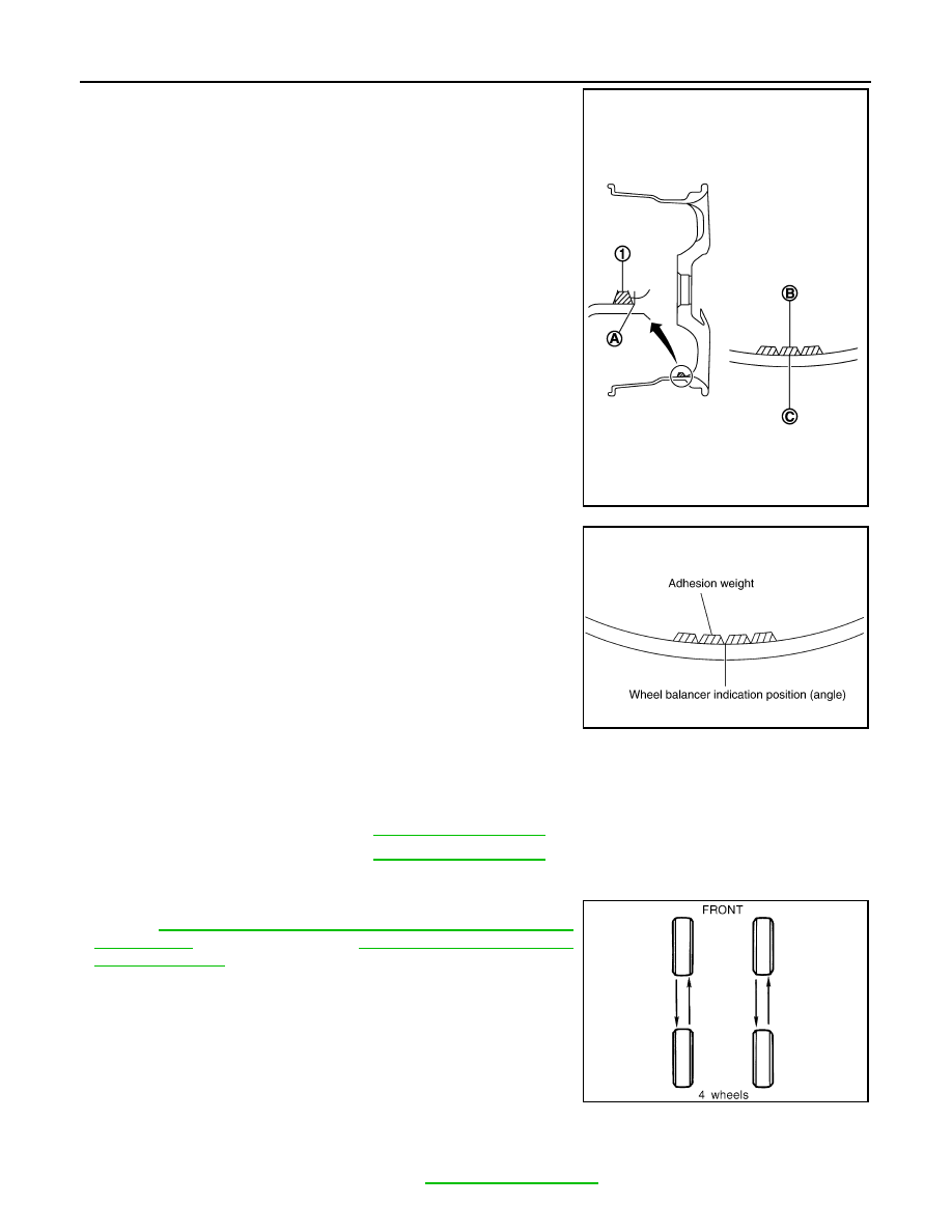
• When installing balance weight (1) to road wheels, set it into

the grooved area (A) on the inner wall of the road wheel as
shown in the figure so that the balance weight center (B) is
aligned with the tire balance machine indication position
(angle) (C).

CAUTION:

• Always use genuine NISSAN adhesion balance weights.
• Balance weights are non-reusable; always replace with

new ones.

• Do not install more than three sheets of balance weight.

c.

If calculated balance weight value exceeds 50 g (1.76 oz), install
two balance weight sheets in line with each other as shown in
the figure.

CAUTION:

Do not install one balance weight sheet on top of another.

3.

Start the tire balance machine again.

4.

Install drive-in balance weight on inner side of road wheel in the
tire balance machine indication position (angle).

CAUTION:

Do not install more than two balance weight.

5.

Start the tire balance machine. Make sure that inner and outer
residual unbalance values are 5 g (0.17 oz) each or below.

6.

If either residual unbalance value exceeds 5 g (0.17 oz), repeat installation procedures.

TIRE ROTATION

• Follow the maintenance schedule for tire rotation service intervals.

Refer to 

MA-5, "FOR NORTH AMERICA : Explanation of General

Maintenance"

 (For North America), 

MA-7, "FOR MEXICO : Gen-

eral Maintenance"

 (For Mexico).

• When installing the wheel, tighten wheel nuts to the specified

torque.

CAUTION:

• Do not include the T-type spare tire when rotating the tires.
• When installing wheels, tighten them diagonally by dividing

the work two to three times in order to prevent the wheels
from developing any distortion.

• Be careful not to tighten wheel nut at torque exceeding the

criteria for preventing strain of disc rotor.

• Use NISSAN genuine wheel nuts for aluminum wheels.

JPEIC0040ZZ

Limit

Dynamic (At flange):

Refer to 

WT-111, "Road Wheel"

.

Static (At flange):

Refer to 

WT-111, "Road Wheel"

.

PEIA0033E

Wheel nuts tighting torque:

Refer to 

WT-111, "Road Wheel"

.

SMA829C

Revision: 2008 October

2009 Murano

ROAD WHEEL TIRE ASSEMBLY

WT-107

< ON-VEHICLE REPAIR >

C

D

F

G

H

I

J

K

L

M

A

B

WT

N

O

P

• Perform the ID registration, after tire rotation. Refer to 

WT-5, "ID REGISTRATION PROCEDURE : Special

Repair Requirement"

.

Revision: 2008 October

2009 Murano

WT-108

< ON-VEHICLE REPAIR >

TRANSMITTER

TRANSMITTER

Exploded View

INFOID:0000000003376011

Removal and Installation

INFOID:0000000003376012

REMOVAL

1.

Deflate tire. Unscrew transmitter retaining nut and allow transmitter to fall into tire.

2.

Gently bounce tire so that transmitter falls to bottom of tire.
Place on tire changing machine and break both tire beads
ensuring that the transmitter remains at the bottom of the tire.

3.

Turn tire so that valve hole is at bottom and bounce so that
transmitter (1) is near valve hole. Carefully lift tire onto turntable
and position valve hole (and transmitter) 270 degree from
mounting/dismounting head (2).

4.

Lubricate tire well and remove first side of the tire. Reach inside
the tire and remove the transmitter.

INSTALLATION

JPEIC0041GB

1.

Transmitter

2.

Grommet seal

3.

Valve nut

4.

Valve core

5.

Cap

Refer to 

GI-4, "Components"

 for symbols in figure.

SEIA0047E

JPEIC0014GB

Revision: 2008 October

2009 Murano

TRANSMITTER

WT-109

< ON-VEHICLE REPAIR >

C

D

F

G

H

I

J

K

L

M

A

B

WT

N

O

P

1.

Put first side of tire onto rim.

2.

Mount transmitter on rim and tighten nut.

CAUTION:

Speed for tightening nut should be less than 10 rpm.

3.

Place wheel on turntable of tire machine. Ensure that transmitter
(1) is 270 degree from mounting head (2) when second side of
tire is fitted. 
NOTE:
Do not touch transmitter at mounting head.

4.

Lubricate tire well and fit second side of tire as normal. Ensure
that tire does not rotate relative to rim.

5.

Inflate tire and fit to appropriate wheel position.

SEIA0049E

JPEIC0014GB

Revision: 2008 October

2009 Murano

WT-110

< ON-VEHICLE REPAIR >

TIRE PRESSURE RECEIVER

TIRE PRESSURE RECEIVER

Exploded View

INFOID:0000000003537309

Removal and Installation

INFOID:0000000003537310

REMOVAL

1.

Remove the instrument lower panel LH. Refer to 

IP-11, "Exploded View"

.

2.

Disconnect tire pressure receiver (1) harness connector.

3.

Remove Tire pressure receiver mounting screw.

4.

Remove tire pressure receiver.

INSTALLATION

Install is the reverse order of removal.

JPEIC0052ZZ

1.

Tire pressure receiver

2.

Bracket

:

Vehicle front

JPEIC0042ZZ

Revision: 2008 October

2009 Murano

SERVICE DATA AND SPECIFICATIONS (SDS)

WT-111

< SERVICE DATA AND SPECIFICATIONS (SDS) 

C

D

F

G

H

I

J

K

L

M

A

B

WT

N

O

P

SERVICE DATA AND SPECIFICATIONS (SDS)

SERVICE DATA AND SPECIFICATIONS (SDS)

Road Wheel

INFOID:0000000003376013

ALUMINUM WHEEL

Wheel Nut

INFOID:0000000003646521

Tire Air Pressure

INFOID:0000000003376014

Unit: kPa (kg/cm

2

, psi)

Item

Limit

Radial runout

Lateral deflection

Less than 0.3 mm (0.012 in)

Vertical deflection

Allowable unbalance

Dynamic (At flange)

Less than 5 g (0.17 oz) (one side)

Static (At flange)

Less than 10 g (0.35 oz)

Item

Standard

Wheel nut tighting torque

108 N·m (11 kg-m, 80 ft-lb)

Item

Standard

Front

Rear

P235/65R18 104T

230 (2.3, 33)

P235/55R20 102T

230 (2.3, 33)

T165/90D18 107M

420 (4.2, 60)

Revision: 2008 October

2009 Murano

WW-1

DRIVER CONTROLS

C

D

E

F

G

H

I

J

K

M

SECTION 

WW

A

B

WW

N

O

P

CONTENTS

WIPER & WASHER

BASIC INSPECTION  ....................................

3

DIAGNOSIS AND REPAIR WORKFLOW  ..........

3

Work Flow  .................................................................

3

FUNCTION DIAGNOSIS ...............................

5

FRONT WIPER AND WASHER SYSTEM  ..........

5

WITH RAIN SENSOR  ..................................................

5

WITH RAIN SENSOR : System Diagram ..................

5

WITH RAIN SENSOR : System Description  .............

5

WITH RAIN SENSOR : Component Parts Loca-
tion ..........................................................................
..

8

WITH RAIN SENSOR : Component Description ......

8

WITHOUT RAIN SENSOR  ..........................................

9

WITHOUT RAIN SENSOR : System Diagram  ..........

9

WITHOUT RAIN SENSOR : System Description ......

9

WITHOUT RAIN SENSOR : Component Parts Lo-
cation .......................................................................

12

WITHOUT RAIN SENSOR : 
Component Description ..........................................

12

REAR WIPER AND WASHER SYSTEM  ...........

14

System Diagram ......................................................

14

System Description  .................................................

14

Component Parts Location ......................................

16

Component Description ..........................................

16

DIAGNOSIS SYSTEM (BCM)  ............................

17

COMMON ITEM  .........................................................

17

COMMON ITEM : CONSULT-III Function (BCM - 
COMMON ITEM) .....................................................

17

WIPER .......................................................................

18

WIPER : CONSULT-III Function (BCM - WIPER) ....

18

DIAGNOSIS SYSTEM (IPDM E/R) .....................

20

Diagnosis Description  .............................................

20

CONSULT-III Function (IPDM E/R) .........................

22

COMPONENT DIAGNOSIS .........................

25

WIPER AND WASHER FUSE, FUSIBLE LINK 

...

25

Description ...............................................................

25

Diagnosis Procedure  ...............................................

25

POWER SUPPLY AND GROUND CIRCUIT  ....

26

BCM (BODY CONTROL MODULE)  ..........................

26

BCM (BODY CONTROL MODULE) : Diagnosis 
Procedure ................................................................

26

IPDM E/R (INTELLIGENT POWER DISTRIBU-
TION MODULE ENGINE ROOM)  ..............................

26

IPDM E/R (INTELLIGENT POWER DISTRIBU-
TION MODULE ENGINE ROOM) : Diagnosis Pro-
cedure ......................................................................

26

FRONT WIPER MOTOR LO CIRCUIT ..............

28

Component Function Check  ....................................

28

Diagnosis Procedure  ...............................................

28

FRONT WIPER MOTOR HI CIRCUIT  ...............

30

Component Function Check  ....................................

30

Diagnosis Procedure  ...............................................

30

FRONT WIPER AUTO STOP SIGNAL CIR-
CUIT ..................................................................

32

Component Function Check  ....................................

32

Diagnosis Procedure  ...............................................

32

FRONT WIPER MOTOR GROUND CIRCUIT ...

34

Diagnosis Procedure  ...............................................

34

WASHER SWITCH ............................................

35

Description ...............................................................

35

Component Inspection .............................................

35

RAIN SENSOR ..................................................

36

Description ...............................................................

36

Component Function Check  ....................................

36

Diagnosis Procedure  ...............................................

36

Revision: 2008 October

2009 Murano

WW-2

REAR WIPER MOTOR CIRCUIT  ......................

38

Component Function Check  ...................................

38

Diagnosis Procedure  ..............................................

38

REAR WIPER AUTO STOP SIGNAL CIRCUIT 

...

40

Component Function Check  ...................................

40

Diagnosis Procedure  ..............................................

40

FRONT WIPER AND WASHER SYSTEM .........

42

Wiring Diagram - FRONT WIPER AND WASHER 
SYSTEM - ..............................................................
.

42

REAR WIPER AND WASHER SYSTEM  ...........

48

Wiring Diagram - REAR WIPER AND WASHER 
SYSTEM - ..............................................................
.

48

ECU DIAGNOSIS  ........................................

52

BCM (BODY CONTROL MODULE)  ..................

52

Reference Value  .....................................................

52

Wiring Diagram - BCM -  .........................................

76

Fail-safe ..................................................................

90

DTC Inspection Priority Chart ..............................

93

DTC Index ..............................................................

94

IPDM E/R (INTELLIGENT POWER DISTRI-
BUTION MODULE ENGINE ROOM)  .................

97

Reference Value  .....................................................

97

Wiring Diagram - IPDM E/R - .................................

105

Fail-safe .................................................................

108

DTC Index .............................................................

110

SYMPTOM DIAGNOSIS  ............................

111

WIPER AND WASHER SYSTEM SYMPTOMS 

.

111

WITH RAIN SENSOR ...............................................

111

WITH RAIN SENSOR : Symptom Table ................

111

WITHOUT RAIN SENSOR  .......................................

113

WITHOUT RAIN SENSOR : Symptom Table  ........

113

NORMAL OPERATING CONDITION  ..............

116

Description .............................................................

116

FRONT WIPER DOES NOT OPERATE  ..........

117

Description .............................................................

117

Diagnosis Procedure  .............................................

117

PRECAUTION ............................................

119

PRECAUTIONS  ...............................................

119

Precaution for Supplemental Restraint System 
(SRS) "AIR BAG" and "SEAT BELT PRE-TEN-
SIONER" ................................................................

119

Precaution for Procedure without Cowl Top Cover .

119

ON-VEHICLE REPAIR  ..............................

120

WASHER TANK  ...............................................

120

Exploded View  ......................................................

120

Removal and Installation .......................................

120

WASHER PUMP ...............................................

121

Exploded View  ......................................................

121

Removal and Installation .......................................

121

WASHER LEVEL SWITCH  ..............................

122

Removal and Installation .......................................

122

FRONT WASHER NOZZLE AND TUBE  ..........

123

Exploded View  ......................................................

123

Hydraulic Layout  ...................................................

123

Removal and Installation .......................................

123

Inspection and Adjustment ....................................

124

FRONT WIPER ARM  ........................................

126

Exploded View  ......................................................

126

Removal and Installation .......................................

126

Adjustment ............................................................

126

WIPER BLADE  .................................................

128

Exploded View  ......................................................

128

Removal and Installation .......................................

128

Replacement .........................................................

128

FRONT WIPER DRIVE ASSEMBLY  ................

130

Exploded View  ......................................................

130

Removal and Installation .......................................

130

Disassembly and Assembly  ..................................

131

RAIN SENSOR  .................................................

132

Exploded View  ......................................................

132

Removal and Installation .......................................

132

WIPER AND WASHER SWITCH  .....................

133

Exploded View  ......................................................

133

REAR WIPER ARM  ..........................................

134

Exploded View  ......................................................

134

Removal and Installation .......................................

134

Adjustment ............................................................

134

REAR WIPER MOTOR .....................................

136

Exploded View  ......................................................

136

Removal and Installation .......................................

136

REAR WASHER NOZZLE AND TUBE  ............

137

Hydraulic Layout  ...................................................

137

Removal and Installation .......................................

137

Inspection and Adjustment ....................................

138

Revision: 2008 October

2009 Murano

DIAGNOSIS AND REPAIR WORKFLOW

WW-3

< BASIC INSPECTION >

C

D

E

F

G

H

I

J

K

M

A

B

WW

N

O

P

BASIC INSPECTION

DIAGNOSIS AND REPAIR WORKFLOW

Work Flow

INFOID:0000000003307601

OVERALL SEQUENCE

DETAILED FLOW

1.

INTERVIEW FOR MALFUNCTION

Interview the symptom to the customer.

JPLIA0313GB

Revision: 2008 October

2009 Murano

WW-4

< BASIC INSPECTION >

DIAGNOSIS AND REPAIR WORKFLOW

>> GO TO 2.

2.

SYMPTOM CHECK

Check the symptom from the customer's information.

>> GO TO 3.

3.

BASIC INSPECTION

Check the operation of each part. Check that any symptom occurs other than the interviewed symptom.

>> GO TO 4.

4.

SELF-DIAGNOSIS WITH CONSULT-III

Perform the self-diagnosis with CONSULT-III. Check that any DTC is detected.
Is any DTC detected?

YES

>> GO TO 5.

NO

>> GO TO 6.

5.

TROUBLE DIAGNOSIS BY DTC

Perform the trouble diagnosis for the detected DTC. Specify the malfunctioning part.

>> GO TO 9.

6.

FAIL-SAFE ACTIVATION CHECK

Check that the symptom is applied to the fail-safe activation.
Does the fail-safe activate?

YES

>> GO TO 7.

NO

>> GO TO 8.

7.

SYSTEM DIAGNOSIS

Perform the system diagnosis for the system that the fail-safe activates. Specify the malfunctioning part.

>> GO TO 9.

8.

SYMPTOM DIAGNOSIS

Perform the symptom diagnosis. Specify the malfunctioning part.

>> GO TO 9.

9.

MALFUNCTION PART REPAIR

Repair or replace the malfunctioning part.

>> GO TO 10.

10.

REPAIR CHECK (SELF-DIAGNOSIS WITH CONSULT-III)

Perform the self-diagnosis with CONSULT-III. Check that any DTC is not detected. Erase DTC if DTC is
detected before the repair. Check that DTC is not detected again.

Is any DTC detected?

YES

>> GO TO 5.

NO

>> GO TO 11.

11.

REPAIR CHECK (OPERATION CHECK)

Check the operation of each part.
Does it operate normally?

YES

>> INSPECTION END

NO

>> GO TO 3.

Revision: 2008 October

2009 Murano

FRONT WIPER AND WASHER SYSTEM

WW-5

< FUNCTION DIAGNOSIS >

C

D

E

F

G

H

I

J

K

M

A

B

WW

N

O

P

FUNCTION DIAGNOSIS

FRONT WIPER AND WASHER SYSTEM

WITH RAIN SENSOR

WITH RAIN SENSOR : System Diagram

INFOID:0000000003307602

WITH RAIN SENSOR : System Description

INFOID:0000000003307603

OUTLINE

The front wiper is controlled by each function of BCM and IPDM E/R.

Control by BCM

• Combination switch reading function
• Front wiper control function

Control by IPDM E/R

• Front wiper control function
• Relay control function
Combination meter indicates low washer fluid warning judged with the signal from the washer level switch. For
details of low washer fluid warning, refer to 

MWI-26, "INFORMATION DISPLAY : System Description"

.

FRONT WIPER BASIC OPERATION

• BCM detects the combination switch condition by the combination switch reading function.
• BCM transmits the front wiper request signal to IPDM E/R with CAN communication depending on each

operating condition of the front wiper.

• IPDM E/R turns ON/OFF the integrated front wiper relay and the front wiper high relay according to the front

wiper request signal. IPDM E/R provides the power supply to operate the front wiper HI/LO operation.

FRONT WIPER LO OPERATION

• BCM transmits the front wiper request signal (LO) to IPDM E/R with CAN communication according to the

front wiper LO operating condition.

Front wiper LO operating condition

- Ignition switch ON
- Front wiper switch LO or front wiper switch MIST (while pressing)
• IPDM E/R turns ON the integrated front wiper relay according to the front wiper request signal (LO).

FRONT WIPER HI OPERATION

• BCM transmits the front wiper request signal (HI) to IPDM E/R with CAN communication according to the

front wiper HI operating condition.

Front wiper HI operating condition

- Ignition switch ON
- Front wiper switch HI

JPLIA1630GB

Revision: 2008 October

2009 Murano

WW-6

< FUNCTION DIAGNOSIS >

FRONT WIPER AND WASHER SYSTEM

• IPDM E/R turns ON the integrated front wiper relay and the front wiper high relay according to the front wiper

request signal (HI).

FRONT WIPER AUTO OPERATION

Rain Sensing

Rain level and sensor conditions are detected by rain sensor.
• BCM transmits the vehicle conditions (vehicle speed, front wiper condition, rain sensor sensitivity setting,

etc.) to the rain sensor via the rain sensor serial link.

• Rain sensor judges a wiping speed for front wiper by rain condition and the vehicle conditions. And it trans-

mits the wiping speed request signal to the BCM via the rain sensor serial link.

Auto Wiping Operation 

• BCM receives the wiping speed request signal from the rain sensor via the rain sensor serial link.
• BCM controls front wiper operation according to the wiping speed request signals. And it transmits the front

wiper request signals (LO or HI) to the IPDM E/R via CAN communication line.

Front wiper AUTO operating condition

- Ignition switch ON
- Front wiper switch INT/AUTO
NOTE:
When the front wiper switch is turned to INT/AUTO position, front wiper operates once regardless of a rainy
condition.

Rain Sensor Sensitivity Setting

BCM determines rain sensor sensitivity according to a wiper volume.

NOTE:
When the wiper volume is turned up at 1 level with front wiper AUTO operating condition, front wiper operates
once.

FRONT WIPER AUTO STOP OPERATION

• BCM stops transmitting the front wiper request signal when the front wiper switch is turned OFF.
• IPDM E/R detects the front wiper stop position signal from the front wiper motor and detects the front wiper

motor position (stop position/except stop position).

• When the front wiper request signal is stopped, IPDM E/R turns ON the front wiper relay until the front wiper

motor returns to the stop position.

Wiper volume dial position

Sensitivity

1

High sensitivity

2

3

Medium

high sensitivity

4

5

Low

medium sensitivity

6

7

Low sensitivity

JPLIA0410GB

Revision: 2008 October

2009 Murano

FRONT WIPER AND WASHER SYSTEM

WW-7

< FUNCTION DIAGNOSIS >

C

D

E

F

G

H

I

J

K

M

A

B

WW

N

O

P

NOTE:
• BCM stops the transmitting of the front wiper request signal when the ignition switch is OFF.
• IPDM E/R turns the front wiper relay OFF when the ignition switch is OFF.

FRONT WIPER OPERATION LINKED WITH WASHER

• BCM transmits the front wiper request signal (LO) to IPDM E/R with CAN communication according to the

washer linked operating condition of the front wiper.

• BCM transmits the front wiper request signal (LO) so that the front wiper operates approximately 2 times

when the front washer switch OFF is detected.

Washer linked operating condition of front wiper

- Ignition switch ON
- Front washer switch ON (0.4 second or more)
• IPDM E/R turns ON the integrated front wiper relay according to the front wiper request signal (LO).
• The washer pump is grounded through the combination switch with the front washer switch ON.

FAIL-SAFE FUNCTION

Front Wiper control

IPDM E/R performs the fail-safe function when the front wiper auto stop circuit is malfunctioning. Refer to

PCS-30, "Fail-safe"

.

Rain Sensor Malfunction

• BCM judges the rain sensor serial link error by the rain sensor serial link condition and detects the rain sen-

sor malfunction by rain sensor malfunction signal.

• When BCM detects the rain sensor serial link error or the rain sensor malfunction while front wiper AUTO

operation, BCM operates a fail-safe control.
NOTE:
If rain sensor malfunction is detected when ignition switch is turned OFF 

 ON and front wiper switch is INT/

AUTO position, BCM operates front wiper LO.

Revision: 2008 October

2009 Murano

WW-8

< FUNCTION DIAGNOSIS >

FRONT WIPER AND WASHER SYSTEM

WITH RAIN SENSOR : Component Parts Location

INFOID:0000000003307604

WITH RAIN SENSOR : Component Description

INFOID:0000000003307605

1.

Combination switch

2.

Combination meter

3.

Rain sensor

4.

Washer pump

5.

Front wiper motor

6.

IPDM E/R

7.

BCM

A.

Wind shield upper

B.

Radiator core support (RH)

C.

Cowl top, left side of engine room

D.

Engine room (left side)

E.

Behind combination meter

JPLIA0883ZZ

Part

Description

BCM

• Judges each switch status by the combination switch reading function.
• Requests (with CAN communication) the front wiper relay and the front wiper high relay ON to 

IPDM E/R.

IPDM E/R

• Controls the integrated relay according to the request (with CAN communication) from BCM.
• Performs the auto stop control of the front wiper.

Revision: 2008 October

2009 Murano

FRONT WIPER AND WASHER SYSTEM

WW-9

< FUNCTION DIAGNOSIS >

C

D

E

F

G

H

I

J

K

M

A

B

WW

N

O

P

WITHOUT RAIN SENSOR

WITHOUT RAIN SENSOR : System Diagram

INFOID:0000000003514393

WITHOUT RAIN SENSOR : System Description

INFOID:0000000003514394

OUTLINE

The front wiper is controlled by each function of BCM and IPDM E/R.

Control by BCM

• Combination switch reading function
• Front wiper control function

Control by IPDM E/R

• Front wiper control function
• Relay control function
Combination meter indicates low washer fluid warning judged with the signal from the washer level switch. For
details of low washer fluid warning, refer to 

MWI-26, "INFORMATION DISPLAY : System Description"

.

FRONT WIPER BASIC OPERATION

• BCM detects the combination switch condition by the combination switch reading function.
• BCM transmits the front wiper request signal to IPDM E/R with CAN communication depending on each

operating condition of the front wiper.

• IPDM E/R turns ON/OFF the integrated front wiper relay and the front wiper high relay according to the front

wiper request signal. IPDM E/R provides the power supply to operate the front wiper HI/LO operation.

FRONT WIPER LO OPERATION

• BCM transmits the front wiper request signal (LO) to IPDM E/R with CAN communication according to the

front wiper LO operating condition.

Front wiper LO operating condition

- Ignition switch ON
- Front wiper switch LO or front wiper switch MIST (while pressing)
• IPDM E/R turns ON the integrated front wiper relay according to the front wiper request signal (LO).

FRONT WIPER HI OPERATION

• BCM transmits the front wiper request signal (HI) to IPDM E/R with CAN communication according to the

front wiper HI operating condition.

Combination switch
(Wiper & washer switch)

Refer to 

BCS-9, "System Diagram"

.

Combination meter

Transmits the vehicle speed signal to BCM with CAN communication.

Rain sensor

Detects water droplets on the windshield with infrared rays, and transmits the rain sensor signal 
to BCM through the rain sensor serial link.

Part

Description

JPLIA1261GB

Revision: 2008 October

2009 Murano

WW-10

< FUNCTION DIAGNOSIS >

FRONT WIPER AND WASHER SYSTEM

Front wiper HI operating condition

- Ignition switch ON
- Front wiper switch HI
• IPDM E/R turns ON the integrated front wiper relay and the front wiper high relay according to the front wiper

request signal (HI).

FRONT WIPER INT OPERATION

• BCM transmits the front wiper request signal (INT) to IPDM E/R with CAN communication depending on the

front wiper INT operating condition and intermittent operation delay interval according to the wiper intermit-
tent dial position.

Front wiper INT operating condition

- Ignition switch ON
- Front wiper switch INT
• IPDM E/R turns ON the integrated front wiper relay so that the front wiper is operated only once according to

the front wiper request signal (INT).

• BCM detects stop position/except stop position of the front wiper motor according to the front wiper stop

position signal received from IPDM E/R with CAN communication.

• BCM transmits the front wiper request signal (INT) again after the intermittent operation delay interval.

NOTE:
Factory setting of the front wiper intermittent operation is the operation without vehicle speed. Front wiper
intermittent operation can be set to the operation with vehicle speed by CONSULT-III. Refer to 

WW-18,

"WIPER : CONSULT-III Function (BCM - WIPER)"

.

Front wiper intermittent operation with vehicle speed

• BCM calculates the intermittent operation delay interval from the following
- Vehicle speed signal (received from the combination meter with CAN communication)
- Wiper intermittent dial position

*: When without vehicle speed setting

FRONT WIPER AUTO STOP OPERATION

• BCM stops transmitting the front wiper request signal when the front wiper switch is turned OFF.
• IPDM E/R detects the front wiper stop position signal from the front wiper motor and detects the front wiper

motor position (stop position/except stop position).

Wiper intermittent 

dial position

Intermittent 

operation 

interval

Intermittent operation delay Interval (s)

Vehicle speed

0 – 5 km/h

(0 – 3.1 MPH)

5 – 35 km/h

(3.1 – 21.7 MPH)

35 – 65 km/h*

(21.7 – 40.4 MPH)

65 km/h (40.4 MPH) 

or more

1

Short

Long

0.8

0.6

0.4

0.24

2

4

3

2

1.2

3

10

7.5

5

3

4

16

12

8

4.8

5

24

18

12

7.2

6

32

24

16

9.6

7

42

31.5

21

12.6

JPLIA1256GB

Revision: 2008 October

2009 Murano


Content      ..     405      406      407      408     ..