Nissan Murano Z51 (2008 year). Manual - part 247


  Index      Manuals     Nissan Murano Z51 (2008 year) - Service and Repair Manual


Search            copyright infringement  


Content      ..     245      246      247      248     ..


Nissan Murano Z51 (2008 year). Manual - part 247


IP-16

< ON-VEHICLE REPAIR >

INSTRUMENT PANEL ASSEMBLY

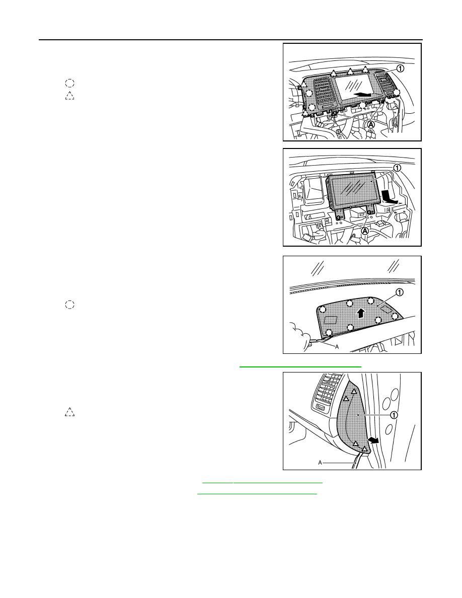
21. Remove center ventilator assembly.

• Remove center ventilator assembly (1) fixing screws (A).
• Pull back center ventilator assembly.

22. Remove display unit.

• Remove display unit (1) fixing screws (A).
• Pull toward the arrow direction.
• Disconnect harness connector.

23. Remove center speaker grille.

• Disengage center speaker grille (1) fixing clips with remover

tool (A).

• Pull up center speaker grille.

24. Remove center speaker. (with BOSE audio) Refer to 

AV-531, "Removal and Installation"

.

25. Remove instrument side finisher RH.

• Insert a remover tool (A) into lower space.
• Pull the instrument side finisher RH (1) crosswise.

26. Remove front body side welt RH. Refer to 

INT-19, "Removal and Installation"

.

27. Remove front pillar garnish RH. Refer to 

INT-19, "Removal and Installation"

.

: Clip

: Pawl

JMJIA1325ZZ

JMJIA1326ZZ

: Clip

JMJIA1327ZZ

: Pawl

JMJIA1328ZZ

Revision: 2008 October

2009 Murano

INSTRUMENT PANEL ASSEMBLY

IP-17

< ON-VEHICLE REPAIR >

C

D

E

F

G

H

I

K

L

M

A

B

IP

N

O

P

28. Remove speaker grille RH.

Pull up speaker grille RH (1).

29. Remove front squawker RH. Refer to 

AV-41, "Removal and Installation"

.

30. Remove optical sensor. (with XENON headlamp) Refer to 

EXL-178, "Removal and Installation"

.

31. Remove instrument lower panel RH.

• Remove instrument lower panel RH (1) fixing screws (A).
• Open the glove box lid (2).
• Remove instrument lower panel RH fixing screws (B).
• Pull back instrument lower panel RH.
• Disconnect harness connector.

32. Disconnect front passenger air bag module connector. Refer to 

SR-11, "Exploded View"

.

33. Remove front passenger air bag module fixing bolt. Refer to 

SR-11, "Exploded View"

.

34. Remove instrument panel assembly (1) mounting screws (A) and bolt (B).

: Pawl

JMJIA1329ZZ

: Pawl

: Metal clip

JMJIA1330ZZ

JMJIA1331ZZ

Revision: 2008 October

2009 Murano

IP-18

< ON-VEHICLE REPAIR >

INSTRUMENT PANEL ASSEMBLY

35. Remove instrument panel assembly.

CAUTION:

• Cover center console upper surface with a shop cloth to prevent it from being damaged.
• When removing instrument panel assembly, 2 workers are required so as to prevent it from drop-

ping.

36. Remove the following parts after removing instrument panel assembly.

• Passenger air bag module. Refer to 

SR-11, "Removal and Installation"

.

• Ventilator duct. Refer to 

VTL-50, "VENTILATOR DUCT : Removal and Installation"

.

• Upper ventilator duct. Refer to 

VTL-51, "UPPER VENTILATOR DUCT : Removal and Installation"

.

• Defroster nozzle and side defroster nozzle LH/RH. Refer to 

VTL-52, "DEFROSTER NOZZLE AND SIDE

DEFROSTER NOZZLE : Removal and Installation"

.

• Side defroster grille LH/RH. Refer to 

VTL-49, "SIDE DEFROSTER GRILLE : Removal and Installation"

.

• Side ventilator grille LH/RH. Refer to 

VTL-47, "SIDE VENTILATOR GRILLE : Removal and Installation"

.

• Antenna feeder. Refer to 

AV-44, "Harness Layout"

.

INSTALLATION

Install in the reverse order of removal.

Revision: 2008 October

2009 Murano

CENTER CONSOLE ASSEMBLY

IP-19

< ON-VEHICLE REPAIR >

C

D

E

F

G

H

I

K

L

M

A

B

IP

N

O

P

CENTER CONSOLE ASSEMBLY

Exploded View

INFOID:0000000003350447

1.

Instrument lower cover RH

2.

Instrument lower cover LH

3.

Instrument stay LH

4.

Front console bracket

5.

Console reinforcement

6.

Lower console finisher LH

7.

Console harness

8.

Inside key antenna

9.

Rear console pocket

10. Console mask

11.

Console rear finisher

12. Auxiliary input jacks

13. Center console assembly

14. Socket and bulb

15. Console finisher assembly

16. Cup holder assembly

17. Ashtray

18. Cigarette lighter complete

19. Cigarette lighter ring

20. Socket knob

21. Socket inner case

22. Console mat

23. Console switch finisher

24. DVD unit

25. Socket knob

26. Socket inner case

27. Lower console assembly

28. Lower console finisher RH

29. Front console pocket

JMJIA1333ZZ

Revision: 2008 October

2009 Murano

IP-20

< ON-VEHICLE REPAIR >

CENTER CONSOLE ASSEMBLY

Removal and Installation

INFOID:0000000003350448

REMOVAL

1.

Remove selector lever knob. Refer to 

TM-165, "Removal and Installation"

.

2.

Remove console finisher assembly.
• Open the console lid.
• Remove console finisher assembly (1) fixing pawls and metal

clips with remover tool (A).

• Pull up console finisher assembly.
• Disconnect harness connectors.

3.

Remove front console pocket.
• Remove front console pocket (1) fixing screw (A).
• Pull up front console pocket, and then disengage metal clips.
• Disconnect harness connectors.

4.

Remove rear console pocket.
• Open the rear console pocket (1).
• Release rear console pocket lock.

5.

Remove console rear finisher.
• Remove console mask (1) with flat-bladed screwdriver (A).

: Pawl

: Metal clip

JMJIA1334ZZ

: Metal clip

JMJIA1335ZZ

JMJIA1336ZZ

: Pawl

JMJIA1337ZZ

Revision: 2008 October

2009 Murano

CENTER CONSOLE ASSEMBLY

IP-21

< ON-VEHICLE REPAIR >

C

D

E

F

G

H

I

K

L

M

A

B

IP

N

O

P

• Remove console rear finisher (2) fixing screws (A).
• Pull back console rear finisher.
• Disconnect harness connectors.

6.

Remove center console assembly.
• Remove center console assembly (1) fixing screws (A).
• Lift up back side and pull back.

7.

Remove instrument lower cover LH/RH.
• Disengage instrument lower cover LH (1) fixing pawls.
• Pull back instrument lower cover LH.
• Disengage instrument lower cover RH (2) fixing pawls and

clip.

• Pull the instrument lower cover RH crosswise.

8.

Remove lower console finisher LH/RH.
• Remove lower console finisher LH (1) fixing screws (A).
• Remove lower console finisher LH fixing clip (B).
• Remove lower console finisher LH fixing clip (C).
• Pull the console finisher LH crosswise.
• Remove lower console finisher RH (2) fixing screws (D).
• Remove lower console finisher RH fixing clip (E).
• Remove lower console finisher RH fixing clip (F).
• Pull the console finisher RH crosswise.

9.

Remove lower console assembly.
• Remove lower console assembly (1) fixing screws (A).
• Remove lower console assembly fixing bolts (B).
• Disconnect harness connectors.

: Metal clip

JMJIA1401ZZ

JMJIA1338ZZ

: Clip

: Pawl

JMJIA1339ZZ

: Clip

JMJIA1340ZZ

JMJIA1341ZZ

Revision: 2008 October

2009 Murano

IP-22

< ON-VEHICLE REPAIR >

CENTER CONSOLE ASSEMBLY

10. Remove DVD player. Refer to 

AV-526, "Removal and Installation"

.

11. Remove control device assembly. Refer to 

TM-165, "Removal and Installation"

.

12. Remove console reinforcement.

• Remove console reinforcement (1) fixing nuts (A).
• Remove console reinforcemen fixing bolts (B).
• Remove harness clip.

13. Remove instrument stay LH fixing nuts, and then remove instrument stay LH.
14. Remove front console bracket fixing bolt and nuts, and then remove front console bracket.

INSTALLATION

Install in the reverse order of removal.

: Clip

JMJIA1342ZZ

Revision: 2008 October

2009 Murano

LAN

LAN-1

ELECTRICAL & POWER CONTROL

C

D

E

F

G

H

I

J

K

L

B

SECTION 

LAN

A

O

P

N

CONTENTS

LAN SYSTEM

CAN FUNDAMENTAL

PRECAUTION ...............................................

6

PRECAUTIONS ...................................................

6

Precautions for Trouble Diagnosis  ............................

6

Precautions for Harness Repair  ................................

6

FUNCTION DIAGNOSIS ...............................

7

CAN COMMUNICATION SYSTEM  .....................

7

System Description  ...................................................

7

System Diagram ........................................................

7

CAN Communication Control Circuit .........................

8

DIAG ON CAN  .....................................................

9

Description ................................................................

9

System Diagram ........................................................

9

TROUBLE DIAGNOSIS  .....................................

10

Condition of Error Detection ....................................

10

Symptom When Error Occurs in CAN Communi-
cation System ..........................................................

10

CAN Diagnosis with CONSULT-III  ..........................

13

Self-Diagnosis .........................................................

13

CAN Diagnostic Support Monitor  ............................

13

How to Use CAN Communication Signal Chart  ......

15

BASIC INSPECTION  ...................................

16

DIAGNOSIS AND REPAIR WORKFLOW  .........

16

Trouble Diagnosis Flow Chart  .................................

16

Trouble Diagnosis Procedure ..................................

16

CAN

HOW TO USE THIS MANUAL .....................

21

HOW TO USE THIS SECTION ...........................

21

Caution ....................................................................

21

Abbreviation List ......................................................

21

PRECAUTION ..............................................

22

PRECAUTIONS .................................................

22

Precaution for Supplemental Restraint System 
(SRS) "AIR BAG" and "SEAT BELT PRE-TEN-
SIONER" .................................................................

22

Precautions for Trouble Diagnosis  ..........................

22

Precautions for Harness Repair  ..............................

22

BASIC INSPECTION  ...................................

24

DIAGNOSIS AND REPAIR WORKFLOW  ........

24

Interview Sheet ........................................................

24

FUNCTION DIAGNOSIS ..............................

25

CAN COMMUNICATION SYSTEM  ...................

25

CAN System Specification Chart .............................

25

CAN Communication Signal Chart  ..........................

25

COMPONENT DIAGNOSIS .........................

29

CAN COMMUNICATION SYSTEM  ...................

29

Component Parts Location  ......................................

29

Wiring Diagram - CAN SYSTEM -  ...........................

30

MALFUNCTION AREA CHART ........................

36

Main Line  .................................................................

36

Branch Line  .............................................................

36

Short Circuit .............................................................

36

MAIN LINE BETWEEN ADP AND PWBD CIR-
CUIT ..................................................................

37

Diagnosis Procedure  ...............................................

37

MAIN LINE BETWEEN PWBD AND M&A CIR-
CUIT ..................................................................

38

Diagnosis Procedure  ...............................................

38

MAIN LINE BETWEEN M&A AND DLC CIR-
CUIT ..................................................................

39

Diagnosis Procedure  ...............................................

39

Revision: 2008 October

2009 Murano

LAN-2

MAIN LINE BETWEEN DLC AND TCM CIR-
CUIT ...................................................................

40

Diagnosis Procedure  ..............................................

40

ECM BRANCH LINE CIRCUIT  ..........................

41

Diagnosis Procedure  ..............................................

41

ADP BRANCH LINE CIRCUIT  ..........................

42

Diagnosis Procedure  ..............................................

42

PWBD BRANCH LINE CIRCUIT  .......................

43

Diagnosis Procedure  ..............................................

43

4WD BRANCH LINE CIRCUIT  ..........................

44

Diagnosis Procedure  ..............................................

44

AV BRANCH LINE CIRCUIT  .............................

45

Diagnosis Procedure  ..............................................

45

HVAC BRANCH LINE CIRCUIT  ........................

46

Diagnosis Procedure  ..............................................

46

M&A BRANCH LINE CIRCUIT  ..........................

47

Diagnosis Procedure  ..............................................

47

A-BAG BRANCH LINE CIRCUIT  ......................

48

Diagnosis Procedure  ..............................................

48

BCM BRANCH LINE CIRCUIT  ..........................

49

Diagnosis Procedure  ..............................................

49

DLC BRANCH LINE CIRCUIT ...........................

50

Diagnosis Procedure  ..............................................

50

STRG BRANCH LINE CIRCUIT  ........................

51

Diagnosis Procedure  ..............................................

51

ABS BRANCH LINE CIRCUIT  ..........................

52

Diagnosis Procedure  ..............................................

52

TCM BRANCH LINE CIRCUIT  ..........................

53

Diagnosis Procedure  ..............................................

53

IPDM-E BRANCH LINE CIRCUIT  .....................

54

Diagnosis Procedure  ..............................................

54

CAN COMMUNICATION CIRCUIT ....................

55

Diagnosis Procedure  ..............................................

55

CAN SYSTEM (TYPE  1)

COMPONENT DIAGNOSIS  ........................

57

MAIN LINE BETWEEN M&A AND DLC CIR-
CUIT ...................................................................

57

Diagnosis Procedure  ..............................................

57

MAIN LINE BETWEEN DLC AND TCM CIR-
CUIT ...................................................................

58

Diagnosis Procedure  ..............................................

58

ECM BRANCH LINE CIRCUIT  ..........................

59

Diagnosis Procedure  ..............................................

59

AV BRANCH LINE CIRCUIT  .............................

60

Diagnosis Procedure ...............................................

60

HVAC BRANCH LINE CIRCUIT ........................

61

Diagnosis Procedure ...............................................

61

M&A BRANCH LINE CIRCUIT ..........................

62

Diagnosis Procedure ...............................................

62

A-BAG BRANCH LINE CIRCUIT  ......................

63

Diagnosis Procedure ...............................................

63

BCM BRANCH LINE CIRCUIT ..........................

64

Diagnosis Procedure ...............................................

64

DLC BRANCH LINE CIRCUIT  ..........................

65

Diagnosis Procedure ...............................................

65

STRG BRANCH LINE CIRCUIT  ........................

66

Diagnosis Procedure ...............................................

66

ABS BRANCH LINE CIRCUIT  ..........................

67

Diagnosis Procedure ...............................................

67

TCM BRANCH LINE CIRCUIT  ..........................

68

Diagnosis Procedure ...............................................

68

IPDM-E BRANCH LINE CIRCUIT  .....................

69

Diagnosis Procedure ...............................................

69

CAN COMMUNICATION CIRCUIT  ...................

70

Diagnosis Procedure ...............................................

70

CAN SYSTEM (TYPE  2)

COMPONENT DIAGNOSIS  .......................

72

MAIN LINE BETWEEN PWBD AND M&A CIR-
CUIT ...................................................................

72

Diagnosis Procedure ...............................................

72

MAIN LINE BETWEEN M&A AND DLC CIR-
CUIT ...................................................................

73

Diagnosis Procedure ...............................................

73

MAIN LINE BETWEEN DLC AND TCM CIR-
CUIT ...................................................................

74

Diagnosis Procedure ...............................................

74

ECM BRANCH LINE CIRCUIT  ..........................

75

Diagnosis Procedure ...............................................

75

PWBD BRANCH LINE CIRCUIT  .......................

76

Diagnosis Procedure ...............................................

76

AV BRANCH LINE CIRCUIT  .............................

77

Diagnosis Procedure ...............................................

77

HVAC BRANCH LINE CIRCUIT ........................

78

Diagnosis Procedure ...............................................

78

M&A BRANCH LINE CIRCUIT ..........................

79

Diagnosis Procedure ...............................................

79

Revision: 2008 October

2009 Murano

LAN

LAN-3

C

D

E

F

G

H

I

J

K

L

B

A

O

P

N

A-BAG BRANCH LINE CIRCUIT  .......................

80

Diagnosis Procedure ...............................................

80

BCM BRANCH LINE CIRCUIT  ..........................

81

Diagnosis Procedure ...............................................

81

DLC BRANCH LINE CIRCUIT  ...........................

82

Diagnosis Procedure ...............................................

82

STRG BRANCH LINE CIRCUIT .........................

83

Diagnosis Procedure ...............................................

83

ABS BRANCH LINE CIRCUIT  ...........................

84

Diagnosis Procedure ...............................................

84

TCM BRANCH LINE CIRCUIT  ...........................

85

Diagnosis Procedure ...............................................

85

IPDM-E BRANCH LINE CIRCUIT  ......................

86

Diagnosis Procedure ...............................................

86

CAN COMMUNICATION CIRCUIT  ....................

87

Diagnosis Procedure ...............................................

87

CAN SYSTEM (TYPE  3)

COMPONENT DIAGNOSIS  .........................

89

MAIN LINE BETWEEN M&A AND DLC CIR-
CUIT ....................................................................

89

Diagnosis Procedure ...............................................

89

MAIN LINE BETWEEN DLC AND TCM CIR-
CUIT ....................................................................

90

Diagnosis Procedure ...............................................

90

ECM BRANCH LINE CIRCUIT ...........................

91

Diagnosis Procedure ...............................................

91

4WD BRANCH LINE CIRCUIT ...........................

92

Diagnosis Procedure ...............................................

92

AV BRANCH LINE CIRCUIT ..............................

93

Diagnosis Procedure ...............................................

93

HVAC BRANCH LINE CIRCUIT  ........................

94

Diagnosis Procedure ...............................................

94

M&A BRANCH LINE CIRCUIT  ..........................

95

Diagnosis Procedure ...............................................

95

A-BAG BRANCH LINE CIRCUIT  .......................

96

Diagnosis Procedure ...............................................

96

BCM BRANCH LINE CIRCUIT  ..........................

97

Diagnosis Procedure ...............................................

97

DLC BRANCH LINE CIRCUIT  ...........................

98

Diagnosis Procedure ...............................................

98

STRG BRANCH LINE CIRCUIT .........................

99

Diagnosis Procedure ...............................................

99

ABS BRANCH LINE CIRCUIT  .........................

100

Diagnosis Procedure  .............................................

100

TCM BRANCH LINE CIRCUIT ........................

101

Diagnosis Procedure  .............................................

101

IPDM-E BRANCH LINE CIRCUIT  ...................

102

Diagnosis Procedure  .............................................

102

CAN COMMUNICATION CIRCUIT  .................

103

Diagnosis Procedure  .............................................

103

CAN SYSTEM (TYPE  4)

COMPONENT DIAGNOSIS .......................

105

MAIN LINE BETWEEN PWBD AND M&A CIR-
CUIT ................................................................

105

Diagnosis Procedure  .............................................

105

MAIN LINE BETWEEN M&A AND DLC CIR-
CUIT ................................................................

106

Diagnosis Procedure  .............................................

106

MAIN LINE BETWEEN DLC AND TCM CIR-
CUIT ................................................................

107

Diagnosis Procedure  .............................................

107

ECM BRANCH LINE CIRCUIT  .......................

108

Diagnosis Procedure  .............................................

108

PWBD BRANCH LINE CIRCUIT  ....................

109

Diagnosis Procedure  .............................................

109

4WD BRANCH LINE CIRCUIT .......................

110

Diagnosis Procedure  .............................................

110

AV BRANCH LINE CIRCUIT  ..........................

111

Diagnosis Procedure  .............................................

111

HVAC BRANCH LINE CIRCUIT  .....................

112

Diagnosis Procedure  .............................................

112

M&A BRANCH LINE CIRCUIT  .......................

113

Diagnosis Procedure  .............................................

113

A-BAG BRANCH LINE CIRCUIT ....................

114

Diagnosis Procedure  .............................................

114

BCM BRANCH LINE CIRCUIT  .......................

115

Diagnosis Procedure  .............................................

115

DLC BRANCH LINE CIRCUIT  ........................

116

Diagnosis Procedure  .............................................

116

STRG BRANCH LINE CIRCUIT  .....................

117

Diagnosis Procedure  .............................................

117

ABS BRANCH LINE CIRCUIT ........................

118

Diagnosis Procedure  .............................................

118

TCM BRANCH LINE CIRCUIT ........................

119

Diagnosis Procedure  .............................................

119

IPDM-E BRANCH LINE CIRCUIT  ...................

120

Revision: 2008 October

2009 Murano

LAN-4

Diagnosis Procedure  .............................................

120

CAN COMMUNICATION CIRCUIT ..................

121

Diagnosis Procedure  .............................................

121

CAN SYSTEM (TYPE  5)

COMPONENT DIAGNOSIS  .......................

123

MAIN LINE BETWEEN ADP AND PWBD CIR-
CUIT .................................................................

123

Diagnosis Procedure  .............................................

123

MAIN LINE BETWEEN PWBD AND M&A CIR-
CUIT .................................................................

124

Diagnosis Procedure  .............................................

124

MAIN LINE BETWEEN M&A AND DLC CIR-
CUIT .................................................................

125

Diagnosis Procedure  .............................................

125

MAIN LINE BETWEEN DLC AND TCM CIR-
CUIT .................................................................

126

Diagnosis Procedure  .............................................

126

ECM BRANCH LINE CIRCUIT  ........................

127

Diagnosis Procedure  .............................................

127

ADP BRANCH LINE CIRCUIT  ........................

128

Diagnosis Procedure  .............................................

128

PWBD BRANCH LINE CIRCUIT  .....................

129

Diagnosis Procedure  .............................................

129

4WD BRANCH LINE CIRCUIT  ........................

130

Diagnosis Procedure  .............................................

130

AV BRANCH LINE CIRCUIT  ...........................

131

Diagnosis Procedure  .............................................

131

HVAC BRANCH LINE CIRCUIT  ......................

132

Diagnosis Procedure  .............................................

132

M&A BRANCH LINE CIRCUIT  ........................

133

Diagnosis Procedure  .............................................

133

A-BAG BRANCH LINE CIRCUIT  ....................

134

Diagnosis Procedure  .............................................

134

BCM BRANCH LINE CIRCUIT  ........................

135

Diagnosis Procedure  .............................................

135

DLC BRANCH LINE CIRCUIT .........................

136

Diagnosis Procedure  .............................................

136

STRG BRANCH LINE CIRCUIT  ......................

137

Diagnosis Procedure  .............................................

137

ABS BRANCH LINE CIRCUIT  ........................

138

Diagnosis Procedure  .............................................

138

TCM BRANCH LINE CIRCUIT  ........................

139

Diagnosis Procedure  .............................................

139

IPDM-E BRANCH LINE CIRCUIT  ....................

140

Diagnosis Procedure .............................................

140

CAN COMMUNICATION CIRCUIT  ..................

141

Diagnosis Procedure .............................................

141

CAN SYSTEM (TYPE  6)

COMPONENT DIAGNOSIS  ......................

143

MAIN LINE BETWEEN M&A AND DLC CIR-
CUIT ..................................................................

143

Diagnosis Procedure .............................................

143

MAIN LINE BETWEEN DLC AND TCM CIR-
CUIT ..................................................................

144

Diagnosis Procedure .............................................

144

ECM BRANCH LINE CIRCUIT  .........................

145

Diagnosis Procedure .............................................

145

HVAC BRANCH LINE CIRCUIT .......................

146

Diagnosis Procedure .............................................

146

M&A BRANCH LINE CIRCUIT .........................

147

Diagnosis Procedure .............................................

147

A-BAG BRANCH LINE CIRCUIT  .....................

148

Diagnosis Procedure .............................................

148

BCM BRANCH LINE CIRCUIT .........................

149

Diagnosis Procedure .............................................

149

DLC BRANCH LINE CIRCUIT  .........................

150

Diagnosis Procedure .............................................

150

STRG BRANCH LINE CIRCUIT  .......................

151

Diagnosis Procedure .............................................

151

ABS BRANCH LINE CIRCUIT  .........................

152

Diagnosis Procedure .............................................

152

TCM BRANCH LINE CIRCUIT  .........................

153

Diagnosis Procedure .............................................

153

IPDM-E BRANCH LINE CIRCUIT  ....................

154

Diagnosis Procedure .............................................

154

CAN COMMUNICATION CIRCUIT  ..................

155

Diagnosis Procedure .............................................

155

CAN SYSTEM (TYPE  7)

COMPONENT DIAGNOSIS  ......................

157

MAIN LINE BETWEEN M&A AND DLC CIR-
CUIT ..................................................................

157

Diagnosis Procedure .............................................

157

MAIN LINE BETWEEN DLC AND TCM CIR-
CUIT ..................................................................

158

Diagnosis Procedure .............................................

158

ECM BRANCH LINE CIRCUIT  .........................

159

Diagnosis Procedure .............................................

159

Revision: 2008 October

2009 Murano

LAN-6

< PRECAUTION >

[CAN FUNDAMENTAL]

PRECAUTIONS

PRECAUTION

PRECAUTIONS

Precautions for Trouble Diagnosis

INFOID:0000000003387561

CAUTION:

• Never apply 7.0 V or more to the measurement terminal.
• Use a tester with open terminal voltage of 7.0 V or less.
• Turn the ignition switch OFF and disconnect the battery cable from the negative terminal when

checking the harness. 

Precautions for Harness Repair

INFOID:0000000003387562

• Solder the repaired area and wrap tape around the soldered area.

NOTE:
A fray of twisted lines must be within 110 mm (4.33 in).

• Bypass connection is never allowed at the repaired area.

NOTE:
Bypass connection may cause CAN communication error. The
spliced wire becomes separated and the characteristics of twisted
line are lost. 

• Replace the applicable harness as an assembly if error is detected on the shield lines of CAN communica-

tion line.

SKIB8766E

SKIB8767E

Revision: 2008 October

2009 Murano

LAN

CAN COMMUNICATION SYSTEM

LAN-7

< FUNCTION DIAGNOSIS >

[CAN FUNDAMENTAL]

C

D

E

F

G

H

I

J

K

L

B

A

O

P

N

FUNCTION DIAGNOSIS

CAN COMMUNICATION SYSTEM

System Description

INFOID:0000000003387563

• CAN communication is a multiplex communication system. This enables the system to transmit and receive

large quantities of data at high speed by connecting control units with two communication lines (CAN-H and
CAN-L).

• Control units on the CAN network transmit signals using the CAN communication control circuit. They

receive only necessary signals from other control units to operate various functions.

• CAN communication lines adopt twisted-pair line style (two lines twisted) for noise immunity.

System Diagram

INFOID:0000000003387564

Each control unit passes an electric current to the termination circuits when transmitting CAN communication
signal. The termination circuits produce an electrical potential difference between CAN-H and CAN-L. CAN
communication system transmits and receives CAN communication signals by the potential difference.

SKIB8887E

Component

Description

Main line

CAN communication line between splices

Branch line

CAN communication line between splice and a control unit

Splice

A point connecting a branch line with a main line

Termination circuit

Refer to 

LAN-8, "CAN Communication Control Circuit"

.

Revision: 2008 October

2009 Murano

LAN-8

< FUNCTION DIAGNOSIS >

[CAN FUNDAMENTAL]

CAN COMMUNICATION SYSTEM

CAN Communication Control Circuit

INFOID:0000000003387565

*: These are the only control units wired with both ends of CAN communication system.

SKIB8713E

Component

System description

CAN controller

It controls CAN communication signal transmission and reception, error detection, etc.

Transceiver IC

It converts digital signal into CAN communication signal, and CAN communication signal into digital 
signal.

Noise filter

It eliminates noise of CAN communication signal.

Termination circuit

*

(Resistance of approx. 120 

)

It produces potential difference.

Revision: 2008 October

2009 Murano

LAN

DIAG ON CAN

LAN-9

< FUNCTION DIAGNOSIS >

[CAN FUNDAMENTAL]

C

D

E

F

G

H

I

J

K

L

B

A

O

P

N

DIAG ON CAN

Description

INFOID:0000000003387566

“Diag on CAN” is a diagnosis using CAN communication instead of previous DDL1 and DDL2 communication
lines, between control units and diagnosis unit.

System Diagram

INFOID:0000000003387567

SKIB8714E

Name

Harness

Description

DDL1

Tx
Rx

It is used for trouble diagnosis. (CAN-H and CAN-L are used for controlling)

DDL2

K-LINE

It is used for trouble diagnosis. (CAN-H and CAN-L are used for controlling)

Diag on CAN

CAN-H
CAN-L

It is used for trouble diagnosis and control.

Revision: 2008 October

2009 Murano


Content      ..     245      246      247      248     ..