Nissan Murano Z51 (2008 year). Manual - part 220
 

  Index      Manuals     Nissan Murano Z51 (2008 year) - Service and Repair Manual


Search            copyright infringement  


Content      ..     218      219      220      221     ..


Nissan Murano Z51 (2008 year). Manual - part 220


HA-56

< ON-VEHICLE REPAIR >

EVAPORATOR PIPE ASSEMBLY

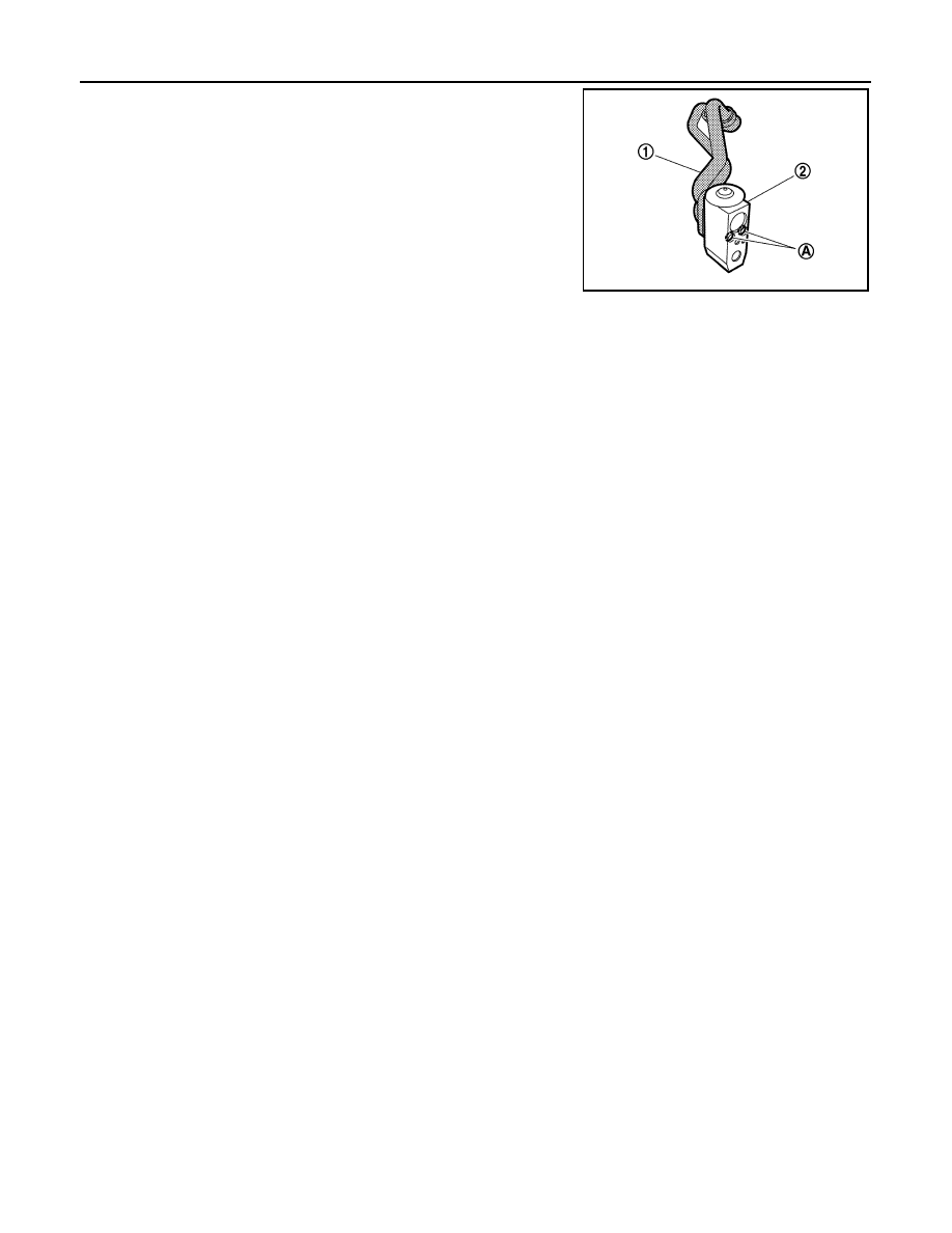
10. Remove the mounting bolts (A), and then remove the evaporator

pipe (2) from the evaporator assembly (1). 

CAUTION:

Cap or wrap the joint of the A/C piping and expansion valve
with suitable material such as vinyl tape to avoid the entry
of air.

INSTALLATION

Installation is basically the reverse order of removal.

CAUTION:

• Replace O-rings with new ones. Then apply compressor oil to them when installing. 
• Check for leakages when recharging refrigerant.

JPIIA0547ZZ

Revision: 2008 October

2009 Murano

EVAPORATOR

HA-57

< ON-VEHICLE REPAIR >

C

D

E

F

G

H

J

K

L

M

A

B

HA

N

O

P

EVAPORATOR

Exploded View

INFOID:0000000003072996

1.

Ventilator seal

2.

Upper ventilator seal

3.

Defroster seal

4.

Adapter case

5.

Center case

6.

Intake sensor bracket

7.

Intake sensor

8.

Upper ventilator door motor

9.

Upper ventilator door rod

10.

Upper ventilator door lever

11.

Filter cover

12. In-cabin microfilter

13.

Foot duct 1 (right)

14.

Foot duct 2 (right)

15. Air mix door motor (passenger side)

16.

Heater & cooling unit case cover

17.

Evaporator pipe assembly

18. O-ring

19.

Evaporator

20.

Expansion valve

21. Case packing

22.

Grommet

23.

Cooler pipe grommet

24. Drain hose

25.

Heater & cooling unit case (right)

26.

Air mix door (Slide door)

27. Heater pipe support

28.

Heater pipe grommet

29.

Heater & cooling unit case (left)

30. Heater core 

31.

Heater pipe cover

32.

Foot duct 2 (left)

33. Foot duct 1 (left)

34.

Heater duct

35.

Aspirator

36. Aspirator hose

37.

Mode door motor

38.

Main link

39. Rod link

40.

Max. cool door link

41.

Ventilator door link

42. Foot door link

43.

Mode door lever

44.

Defroster door link

45. Ventilator door lever

46.

Foot door lever

47.

Defroster door lever

48. Max. cool door lever

JPIIA0454GB

Revision: 2008 October

2009 Murano

HA-58

< ON-VEHICLE REPAIR >

EVAPORATOR

Removal and Installation

INFOID:0000000003072997

REMOVAL

1.

Remove the evaporator pipe assembly. Refer to 

HA-54, "Exploded View"

2.

Slide the evaporator (1) toward the right side of vehicle.

3.

Remove the intake sensor (2), and then remove the evaporator. 

INSTALLATION

Installation is basically the reverse order of removal.

CAUTION:

• Replace O-rings with new ones. Then apply compressor oil to them when installing. 
• Mark the mounting position of intake sensor bracket prior to removal so that the reinstalled sensor

can be located in the same position.

• Never rotate the bracket insertion part when removing and installing the intake sensor.
• Check for leakages when recharging refrigerant.

49. Air mix door motor (driver side)

50.

Distributor upper case

51.

Distributor lower case

52. Ventilator door

53.

Foot door

54.

Max. cool door

55. Defroster door

56.

Upper ventilator door

Refer to 

GI-4, "Components"

 for symbols in the figure.

JPIIA0907ZZ

Revision: 2008 October

2009 Murano

EXPANSION VALVE

HA-59

< ON-VEHICLE REPAIR >

C

D

E

F

G

H

J

K

L

M

A

B

HA

N

O

P

EXPANSION VALVE

Exploded View

INFOID:0000000003459076

1.

Ventilator seal

2.

Upper ventilator seal

3.

Defroster seal

4.

Adapter case

5.

Center case

6.

Intake sensor bracket

7.

Intake sensor

8.

Upper ventilator door motor

9.

Upper ventilator door rod

10.

Upper ventilator door lever

11.

Filter cover

12. In-cabin microfilter

13.

Foot duct 1 (right)

14.

Foot duct 2 (right)

15. Air mix door motor (passenger side)

16.

Heater & cooling unit case cover

17.

Evaporator pipe assembly

18. O-ring

19.

Evaporator

20.

Expansion valve

21. Case packing

22.

Grommet

23.

Cooler pipe grommet

24. Drain hose

25.

Heater & cooling unit case (right)

26.

Air mix door (Slide door)

27. Heater pipe support

28.

Heater pipe grommet

29.

Heater & cooling unit case (left)

30. Heater core 

31.

Heater pipe cover

32.

Foot duct 2 (left)

33. Foot duct 1 (left)

34.

Heater duct

35.

Aspirator

36. Aspirator hose

37.

Mode door motor

38.

Main link

39. Rod link

40.

Max. cool door link

41.

Ventilator door link

42. Foot door link

43.

Mode door lever

44.

Defroster door link

45. Ventilator door lever

46.

Foot door lever

47.

Defroster door lever

48. Max. cool door lever

JPIIA0454GB

Revision: 2008 October

2009 Murano

HA-60

< ON-VEHICLE REPAIR >

EXPANSION VALVE

Removal and Installation

INFOID:0000000003072999

REMOVAL

1.

Use refrigerant collecting equipment (for HFC-134a) to discharge the refrigerant.

2.

Remove the mounting bolt (A), and then disconnect the low-
pressure pipe (1) and high-pressure pipe (2) from the expansion
valve. 

CAUTION:

Cap or wrap the joint of the A/C piping and expansion valve
with suitable material such as vinyl tape to avoid the entry
of air.

3.

Remove the mounting bolts (A), and then remove the expansion
valve (1). 

CAUTION:

Cap or wrap the joint of the A/C piping and expansion valve
with suitable material such as vinyl tape to avoid the entry
of air.

INSTALLATION

Installation is basically the reverse order of removal.

CAUTION:

• Replace O-rings with new ones. Then apply compressor oil to them when installing. 
• Check for leakages when recharging refrigerant.

49. Air mix door motor (driver side)

50.

Distributor upper case

51.

Distributor lower case

52. Ventilator door

53.

Foot door

54.

Max. cool door

55. Defroster door

56.

Upper ventilator door

Refer to 

GI-4, "Components"

 for symbols in the figure.

JPIIA0561ZZ

JPIIA0549ZZ

Revision: 2008 October

2009 Murano

SERVICE DATA AND SPECIFICATIONS (SDS)

HA-61

< SERVICE DATA AND SPECIFICATIONS (SDS) 

C

D

E

F

G

H

J

K

L

M

A

B

HA

N

O

P

SERVICE DATA AND SPECIFICATIONS (SDS)

SERVICE DATA AND SPECIFICATIONS (SDS)

Compressor

INFOID:0000000003073000

Lubricant

INFOID:0000000003073001

Refrigerant

INFOID:0000000003073002

Engine Idling Speed

INFOID:0000000003073003

Refer to 

EC-551, "Idle Speed"

.

Belt Tension

INFOID:0000000003073004

Refer to 

EM-141, "Drive Belt"

.

Model

VALEO THERMAL SYSTEMS JAPAN make 

DKS-17D

Type

Fixation displacement swash plate

Displacement

cm

3

 (cu in)/rev

Max.

175 (10.7)

Cylinder bore 

×

 stroke (Max.)

mm (in.)

30.5 (1.20) 

×

 24 (0.94)

Direction of rotation

Clockwise (viewed from clutch)

Drive belt

Poly V

Disc to pulley clearance
mm (in.)

Standard

0.3 - 0.6 (0.012 - 0.024)

Name

NISSAN A/C System Oil Type S (DH-PS)

Capacity

m

 (US fl oz, lmp fl oz)

Total in system

150 (5.07, 5.3)

Compressor (service part) charging 
amount

150 (5.07, 5.3)

Type

HFC-134a (R-134a)

Capacity
kg (lb)

0.60 (1.32)

Revision: 2008 October

2009 Murano

HAC-1

VENTILATION, HEATER & AIR CONDITIONER

C

D

E

F

G

H

J

K

L

M

SECTION 

HAC

A

B

HAC

N

O

P

CONTENTS

HEATER & AIR CONDITIONING CONTROL SYSTEM

WITHOUT 7 INCH DISPLAY

BASIC INSPECTION  ....................................

5

DIAGNOSIS AND REPAIR WORKFLOW  ..........

5

Work Flow  .................................................................

5

INSPECTION AND ADJUSTMENT .....................

7

Description & Inspection  ...........................................

7

Temperature Setting Trimmer  ...................................

9

Foot Position Setting Trimmer ...................................

9

Inlet Port Memory Function (FRE)  ..........................

10

Inlet Port Memory Function (REC)  ..........................

10

FUNCTION DIAGNOSIS ..............................

11

COMPRESSOR CONTROL FUNCTION ............

11

Description ..............................................................

11

Component Part Location  .......................................

12

Component’s Role ...................................................

14

AUTOMATIC AIR CONDITIONER SYSTEM  .....

15

System Diagram ......................................................

15

System Description  .................................................

15

Component Part Location  .......................................

22

Component Description ...........................................

25

MODE DOOR CONTROL SYSTEM  ...................

26

System Diagram ......................................................

26

System Description  .................................................

26

UPPER VENTILATOR DOOR CONTROL 
SYSTEM .............................................................

28

System Diagram ......................................................

28

System Description  .................................................

28

AIR MIX DOOR CONTROL SYSTEM  ................

30

System Diagram ......................................................

30

System Description  .................................................

30

INTAKE DOOR CONTROL SYSTEM  ................

32

System Diagram ......................................................

32

System Description ..................................................

32

BLOWER MOTOR CONTROL SYSTEM  ..........

34

System Diagram  ......................................................

34

System Description ..................................................

34

MAGNET CLUTCH CONTROL SYSTEM  .........

36

System Diagram  ......................................................

36

System Description ..................................................

36

CAN COMMUNICATION SYSTEM  ...................

37

System Description ..................................................

37

DIAGNOSIS SYSTEM (HVAC)  .........................

38

CONSULT-III Function  ............................................

38

COMPONENT DIAGNOSIS .........................

42

U1000 CAN COMM CIRCUIT  ...........................

42

Description ...............................................................

42

DTC Logic ................................................................

42

Diagnosis Procedure ..............................................

42

U1010 CONTROL UNIT (CAN) .........................

43

Description ...............................................................

43

DTC Logic ................................................................

43

Diagnosis Procedure  ...............................................

43

B257B, B257C AMBIENT SENSOR .................

44

Description ...............................................................

44

DTC Logic ................................................................

44

Diagnosis Procedure  ...............................................

45

Component Inspection .............................................

46

B2578, B2579 IN-VEHICLE SENSOR  ..............

47

Description ...............................................................

47

DTC Logic ................................................................

47

Diagnosis Procedure  ...............................................

48

Component Inspection .............................................

49

B2581, B2582 INTAKE SENSOR  .....................

50

Description ...............................................................

50

DTC Logic ................................................................

50

Revision: 2008 October

2009 Murano

HAC-2

Diagnosis Procedure  ..............................................

50

Component Inspection ............................................

51

B2630, B2631 SUNLOAD SENSOR  .................

53

Description ..............................................................

53

DTC Logic ...............................................................

53

Diagnosis Procedure  ..............................................

54

Component Inspection ............................................

55

B2632, B2633 AIR MIX DOOR MOTOR 
(DRIVER SIDE)  ..................................................

56

Description ..............................................................

56

DTC Logic ...............................................................

56

Diagnosis Procedure  ..............................................

57

B2634, B2635 AIR MIX DOOR MOTOR (PAS-
SENGER SIDE) ..................................................

58

Description ..............................................................

58

DTC Logic ...............................................................

58

Diagnosis Procedure  ..............................................

59

B2636, B2637, B2638, B2639, B2654, B2655 
MODE DOOR MOTOR  ......................................

60

Description ..............................................................

60

DTC Logic ...............................................................

60

Diagnosis Procedure  ..............................................

61

B263D, B263E, B263F INTAKE DOOR MO-
TOR ....................................................................

63

Description ..............................................................

63

DTC Logic ...............................................................

63

Diagnosis Procedure  ..............................................

64

B2661, B2662, B2663 UPPER VENTILATOR 
DOOR MOTOR  ..................................................

65

Description ..............................................................

65

DTC Logic ...............................................................

65

Diagnosis Procedure  ..............................................

66

BLOWER MOTOR  .............................................

68

Description ..............................................................

68

Component Function Check .................................

68

Diagnosis Procedure  ..............................................

68

Component Inspection ............................................

71

MAGNET CLUTCH  ............................................

72

Description ..............................................................

72

Component Function Check  ...................................

72

Diagnosis Procedure  ..............................................

72

A/C CONTROL SIGNAL CIRCUIT  ....................

74

Diagnosis Procedure  ..............................................

74

POWER SUPPLY AND GROUND CIRCUIT  .....

75

A/C AUTO AMP.  .......................................................

75

A/C AUTO AMP. : Description  ................................

75

A/C AUTO AMP. : Component Function Check  .....

75

A/C AUTO AMP. : Diagnosis Procedure  ................

75

A/C CONTROL ..........................................................

76

A/C CONTROL : Diagnosis Procedure  ...................

76

A/C DISPLAY  ............................................................

77

A/C DISPLAY : Diagnosis Procedure  .....................

77

ECU DIAGNOSIS  .......................................

78

ECM ...................................................................

78

Reference Value  .....................................................

78

A/C AUTO AMP. ................................................

93

Reference Value  .....................................................

93

Wiring Diagram - AIR CONDITIONER CONTROL 
SYSTEM -  ...............................................................

95

Fail-Safe ................................................................

102

DTC Inspection Priority Chart .............................

103

DTC Index .............................................................

103

SYMPTOM DIAGNOSIS  ...........................

105

AIR CONDITIONER CONTROL  .......................

105

Diagnosis Chart By Symptom  ...............................

105

INSUFFICIENT COOLING ................................

106

Description ............................................................

106

Inspection procedure  ............................................

106

INSUFFICIENT HEATING  ................................

109

Description ............................................................

109

Inspection procedure  ............................................

109

NOISE ...............................................................

112

Description ............................................................

112

Inspection procedure  ............................................

112

MEMORY FUNCTION DOES NOT OPERATE ..

114

Description ............................................................

114

Inspection procedure  ............................................

114

PRECAUTION ...........................................

115

PRECAUTIONS  ................................................

115

FOR USA AND CANADA  .......................................

115

FOR USA AND CANADA : Precaution for Supple-
mental Restraint System (SRS) "AIR BAG" and 
"SEAT BELT PRE-TENSIONER"  .........................

115

FOR MEXICO  ..........................................................

115

FOR MEXICO : Precaution for Supplemental Re-
straint System (SRS) "AIR BAG" and "SEAT BELT 
PRE-TENSIONER" ...............................................

115

Precaution Necessary for Steering Wheel Rota-
tion after Battery Disconnect .................................

116

Precaution for Procedure without Cowl Top Cover .

116

Precautions For Xenon Headlamp Service ...........

116

Working with HFC-134a (R-134a) .........................

117

General Refrigerant Precaution  ............................

117

Refrigerant Connection  .........................................

118

Service Equipment ................................................

120

COMPRESSOR  ................................................

122

Revision: 2008 October

2009 Murano

HAC-3

C

D

E

F

G

H

J

K

L

M

A

B

HAC

N

O

P

General Precautions  .............................................

122

FLUORESCENT LEAK DETECTOR  ...............

123

General Precautions  .............................................

123

WITH 7 INCH DISPLAY

BASIC INSPECTION  .................................

124

DIAGNOSIS AND REPAIR WORKFLOW  .......

124

Work Flow  .............................................................

124

INSPECTION AND ADJUSTMENT ..................

126

Description & Inspection  .......................................

126

Temperature Setting Trimmer  ...............................

128

Foot Position Setting Trimmer ...............................

128

Inlet Port Memory Function (FRE)  ........................

129

Inlet Port Memory Function (REC)  ........................

129

FUNCTION DIAGNOSIS ............................

130

COMPRESSOR CONTROL FUNCTION ..........

130

Description ............................................................

130

Fail-Safe ................................................................

131

Component Part Location  .....................................

131

Component’s Role .................................................

134

AUTOMATIC AIR CONDITIONER SYSTEM  ...

135

System Diagram ....................................................

135

System Description  ...............................................

135

Component Part Location  .....................................

141

Component Description .........................................

144

MODE DOOR CONTROL SYSTEM  .................

145

System Diagram ....................................................

145

System Description  ...............................................

145

UPPER VENTILATOR DOOR CONTROL 
SYSTEM ...........................................................

147

System Diagram ....................................................

147

System Description  ...............................................

147

AIR MIX DOOR CONTROL SYSTEM  ..............

149

System Diagram ....................................................

149

System Description  ...............................................

149

INTAKE DOOR CONTROL SYSTEM  ..............

151

System Diagram ....................................................

151

System Description  ...............................................

151

BLOWER MOTOR CONTROL SYSTEM  .........

153

System Diagram ....................................................

153

System Description  ...............................................

153

MAGNET CLUTCH CONTROL SYSTEM  ........

155

System Diagram ....................................................

155

System Description  ...............................................

155

CAN COMMUNICATION SYSTEM  ..................

156

System Description  ...............................................

156

DIAGNOSIS SYSTEM (HVAC)  ........................

157

CONSULT-III Function  ..........................................

157

COMPONENT DIAGNOSIS .......................

161

U1000 CAN COMM CIRCUIT  .........................

161

Description .............................................................

161

DTC Logic ..............................................................

161

Diagnosis Procedure ............................................

161

U1010 CONTROL UNIT (CAN) .......................

162

Description .............................................................

162

DTC Logic ..............................................................

162

Diagnosis Procedure  .............................................

162

B257B, B257C AMBIENT SENSOR ...............

163

Description .............................................................

163

DTC Logic ..............................................................

163

Diagnosis Procedure  .............................................

164

Component Inspection ...........................................

165

B2578, B2579 IN-VEHICLE SENSOR  ............

166

Description .............................................................

166

DTC Logic ..............................................................

166

Diagnosis Procedure  .............................................

167

Component Inspection ...........................................

168

B2581, B2582 INTAKE SENSOR  ...................

169

Description .............................................................

169

DTC Logic ..............................................................

169

Diagnosis Procedure  .............................................

169

Component Inspection ...........................................

170

B2630, B2631 SUNLOAD SENSOR ...............

172

Description .............................................................

172

DTC Logic ..............................................................

172

Diagnosis Procedure  .............................................

173

Component Inspection ...........................................

174

B2632, B2633 AIR MIX DOOR MOTOR 
(DRIVER SIDE)  ...............................................

175

Description .............................................................

175

DTC Logic ..............................................................

175

Diagnosis Procedure  .............................................

176

B2634, B2635 AIR MIX DOOR MOTOR (PAS-
SENGER SIDE)  ...............................................

177

Description .............................................................

177

DTC Logic ..............................................................

177

Diagnosis Procedure  .............................................

178

B2636, B2637, B2638, B2639, B2654, B2655 
MODE DOOR MOTOR ....................................

179

Description .............................................................

179

DTC Logic ..............................................................

179

Diagnosis Procedure  .............................................

180

B263D, B263E, B263F INTAKE DOOR MO-
TOR .................................................................

182

Description .............................................................

182

DTC Logic ..............................................................

182

Diagnosis Procedure  .............................................

183

Revision: 2008 October

2009 Murano

HAC-4

B2661, B2662, B2663 UPPER VENTILATOR 
DOOR MOTOR  ................................................

184

Description .............................................................

184

DTC Logic ..............................................................

184

Diagnosis Procedure  .............................................

185

BLOWER MOTOR  ...........................................

187

Description .............................................................

187

Component Function Check ................................

187

Diagnosis Procedure  .............................................

187

Component Inspection ...........................................

190

MAGNET CLUTCH  ..........................................

191

Description .............................................................

191

Component Function Check  ..................................

191

Diagnosis Procedure  .............................................

191

POWER SUPPLY AND GROUND CIRCUIT  ...

193

A/C AUTO AMP.  ......................................................

193

A/C AUTO AMP. : Description  ...............................

193

A/C AUTO AMP. : Component Function Check  ....

193

A/C AUTO AMP. : Diagnosis Procedure  ...............

193

ECU DIAGNOSIS  .......................................

195

ECM .................................................................

195

Reference Value  ....................................................

195

A/C AUTO AMP.  ..............................................

210

Reference Value  ....................................................

210

Wiring Diagram - AIR CONDITIONER CONTROL 
SYSTEM - ..............................................................

212

Fail-Safe ................................................................

219

DTC Inspection Priority Chart .............................

220

DTC Index  .............................................................

220

SYMPTOM DIAGNOSIS  ............................

222

AIR CONDITIONER CONTROL  ......................

222

Diagnosis Chart By Symptom ................................

222

INSUFFICIENT COOLING  ...............................

223

Description ............................................................

223

Inspection procedure  ............................................

223

INSUFFICIENT HEATING  ................................

226

Description ............................................................

226

Inspection procedure  ............................................

226

NOISE ...............................................................

229

Description ............................................................

229

Inspection procedure  ............................................

229

MEMORY FUNCTION DOES NOT OPERATE ..

231

Description ............................................................

231

Inspection procedure  ............................................

231

PRECAUTION ...........................................

232

PRECAUTIONS  ................................................

232

FOR USA AND CANADA  .......................................

232

FOR USA AND CANADA : Precaution for Supple-
mental Restraint System (SRS) "AIR BAG" and 
"SEAT BELT PRE-TENSIONER"  .........................

232

FOR MEXICO  ..........................................................

232

FOR MEXICO : Precaution for Supplemental Re-
straint System (SRS) "AIR BAG" and "SEAT BELT 
PRE-TENSIONER" ...............................................

232

Precaution Necessary for Steering Wheel Rota-
tion after Battery Disconnect .................................

233

Precaution for Procedure without Cowl Top Cover .

233

Precautions For Xenon Headlamp Service ...........

233

Working with HFC-134a (R-134a) .........................

234

General Refrigerant Precaution  ............................

234

Refrigerant Connection  .........................................

235

Service Equipment ................................................

237

COMPRESSOR  ................................................

239

General Precautions  .............................................

239

FLUORESCENT LEAK DETECTOR ................

240

General Precautions  .............................................

240

Revision: 2008 October

2009 Murano

DIAGNOSIS AND REPAIR WORKFLOW

HAC-5

< BASIC INSPECTION >

[WITHOUT 7 INCH DISPLAY]

C

D

E

F

G

H

J

K

L

M

A

B

HAC

N

O

P

BASIC INSPECTION

DIAGNOSIS AND REPAIR WORKFLOW

Work Flow

INFOID:0000000003073006

OVERALL SEQUENCE

*1: Refer to 

HAC-103, "DTC Index"

.

*2: Refer to 

HAC-105, "Diagnosis Chart By Symptom"

.

DETAILED FLOW

1.

OBTAIN INFORMATION ABOUT SYMPTOM

Interview the customer to obtain as much information as possible about the conditions and environment under
which the malfunction occurred.

>> GO TO 2.

2.

VERIFY SYMPTOM

Verify the symptom with operational check based on the information obtained from the customer. Refer to

HAC-7, "Description & Inspection"

.

>> GO TO 3.

JSIIA0943GB

Revision: 2008 October

2009 Murano

HAC-6

< BASIC INSPECTION >

[WITHOUT 7 INCH DISPLAY]

DIAGNOSIS AND REPAIR WORKFLOW

3.

CHECK WITH SELF-DIAGNOSIS FUNCTION OF CONSULT-III

Using CONSULT-III, perform “SELF-DIAGNOSIS RESULTS” of HVAC. Refer to 

HAC-103, "DTC Index"

.

Are self-diagnosis results normal?

YES

>> GO TO 4.

NO

>> GO TO 5.

4.

NARROW DOWN THE MALFUNCTIONING PARTS BY SYMPTOM DIAGNOSIS

Perform symptom diagnosis and narrow down the malfunctioning parts. Refer to 

HAC-105, "Diagnosis Chart

By Symptom"

.

>> GO TO 5.

5.

REPAIR OR REPLACE

Repair or replace malfunctioning parts.
NOTE:
If DTC is displayed, erase DTC after repairing or replacing malfunctioning parts.

>> GO TO 6.

6.

FINAL CHECK

Check that the A/C system operates normally.

Is the inspection result normal?

YES

>> INSPECTION END

NO

>> GO TO 3.

Revision: 2008 October

2009 Murano

INSPECTION AND ADJUSTMENT

HAC-7

< BASIC INSPECTION >

[WITHOUT 7 INCH DISPLAY]

C

D

E

F

G

H

J

K

L

M

A

B

HAC

N

O

P

INSPECTION AND ADJUSTMENT

Description & Inspection

INFOID:0000000003073011

DESCRIPTION

The purpose of the operational check is to check that the individual system operates normally.

INSPECTION PROCEDURE

1.

CHECK MEMORY FUNCTION

1.

Start the engine.

2.

Operate the temperature control switch (driver side) and raise the temperature setting to 32

°

C (90

°

F). 

3.

Press the OFF switch.

4.

Turn the ignition switch OFF.

5.

Turn the ignition switch ON.

6.

Press the AUTO switch.

7.

Check that the temperature setting before turning the ignition switch OFF is stored. 

Is the inspection result normal?

YES

>> GO TO 2.

NO

>> Memory function malfunction: 

HAC-114, "Inspection procedure"

.

2.

CHECK BLOWER MOTOR SPEED

1.

Start the engine.

2.

Operate the fan control dial. Check that the fan speed changes. Check the operation for all fan speeds. 

3.

Set the fan speed to speed 7.

Is the inspection result normal?

YES

>> GO TO 3.

NO

>> Blower motor system malfunction: 

HAC-68, "Diagnosis Procedure"

.

3.

CHECK DISCHARGE AIR(MODE SWITCH AND DEF SWITCH)

1.

Press the MODE switch and the DEF switch.

2.

Check that the air outlets change according to each indicated air outlet by placing a hand in front of the
outlets. Refer to 

HAC-15, "System Description"

NOTE:
Confirm that the compressor clutch is engaged (sound or visual inspection) and the intake door position is at
the FRE when the D/F or DEF is selected.

Is the inspection result normal?

YES

>> GO TO 4.

NO

>> Mode door system malfunction: 

HAC-61, "Diagnosis Procedure"

.

4.

CHECK DISCHARGE AIR (UPPER VENT SWITCH)

1.

Press the UPPER VENT switch. 

2.

The UPPER VENT switch indicator is turned ON. 

Conditions

: Engine running at normal operating temperature

Revision: 2008 October

2009 Murano

HAC-8

< BASIC INSPECTION >

[WITHOUT 7 INCH DISPLAY]

INSPECTION AND ADJUSTMENT

3.

Check that the air blown from the UPPER VENT does not greatly deviate from the air mix ratio. 

4.

Press the UPPER VENT switch again. 

5.

The UPPER VENT switch indicator is turned OFF. 

6.

The air blown from the UPPER VENT stops. 

Does it operate normally?

YES

>> GO TO 5.

NO

>> Upper ventilator door system malfunction: 

HAC-66, "Diagnosis Procedure"

.

5.

CHECK INTAKE AIR

1.

Press the intake switch. Indicator is turned ON (REC).

2.

Press the intake switch again. Indicator is turned OFF (FRE).

3.

Listen for the intake door position change. (Slight change of blower sound can be heard.)

NOTE:
Confirm that the compressor clutch is engaged (sound or visual inspection) and the intake door position is at
the FRE when the D/F or DEF is selected.

Is the inspection result normal?

YES

>> GO TO 6.

NO

>> Intake door system malfunction: 

HAC-64, "Diagnosis Procedure"

.

6.

CHECK A/C SWITCH

1.

Press the A/C switch.

2.

The A/C switch indicator is turned ON.
Confirm that the compressor clutch engages (sound or visual inspection).

Is the inspection result normal?

YES

>> GO TO 7.

NO

>> Magnet clutch system malfunction: 

HAC-72, "Diagnosis Procedure"

.

7.

CHECK WITH TEMPERATURE SETTING LOWERED

1.

Operate the compressor. 

2.

Operate the temperature control switch (driver side) and lower the temperature setting to 18

°

C (60

°

F). 

3.

Check that the cool air blows from the outlets. 

Is the inspection result normal?

YES

>> GO TO 8.

NO

>> Insufficient cooling: 

HAC-106, "Inspection procedure"

.

8.

CHECK WITH TEMPERATURE SETTING RAISED

1.

Operate the temperature control switch (driver side) and raise the temperature setting to 32

°

C (90

°

F) after

warming up the engine. 

2.

Check that the warm air blows from the outlets.

Is the inspection result normal?

YES

>> GO TO 9.

NO

>> Insufficient heating: 

HAC-109, "Inspection procedure"

.

JPIIA0509GB

Revision: 2008 October

2009 Murano

INSPECTION AND ADJUSTMENT

HAC-9

< BASIC INSPECTION >

[WITHOUT 7 INCH DISPLAY]

C

D

E

F

G

H

J

K

L

M

A

B

HAC

N

O

P

9.

CHECK LH/RH INDEPENDENT TEMPERATURE ADJUSTMENT FUNCTION

1.

Press the DUAL switch, and then check that “DUAL” is shown on the display. 

2.

Operate the temperature control switch (driver side). Check that the discharge air temperature (driver
side) changes. 

3.

Operate the temperature control switch (passenger side). Check that the discharge air temperature (pas-
senger side) changes. 

4.

Press the DUAL switch, and then check that the temperature setting (LH/RH) is unified to the driver side
temperature setting. 

Is the inspection result normal?

YES

>> GO TO 10.

NO

>> Refer to 

HAC-105, "Diagnosis Chart By Symptom"

 and perform the appropriate diagnosis. 

10.

CHECK AUTO MODE

1.

Press the AUTO switch, and then check that “AUTO” is shown on the display. 

2.

Operate the temperature control switch (driver side). Check that the fan speed or outlet changes (the dis-
charge air temperature or fan speed varies depending on the ambient temperature, in-vehicle tempera-
ture, and temperature setting). 

Is the inspection result normal?

YES

>> INSPECTION END

NO

>> Refer to 

HAC-105, "Diagnosis Chart By Symptom"

 and perform the appropriate diagnosis. 

Temperature Setting Trimmer

INFOID:0000000003073012

Description

If the temperature felt by the customer is different than the air flow temperature controlled by the temperature
setting, the auto amplifier control temperature can be adjusted to compensate for the temperature setting. 

How to set

Using CONSULT-III, perform “TEMP SET CORRECT” on “WORK SUPPORT” of HVAC. 

NOTE:

• When the temperature setting is set to 25.0

°

C (77

°

F) and 

3.0

°

C (

6

°

F), the temperature controlled by auto amp is 25.0

°

C (77

°

F) 

3.0

°

C (6

°

F) = 22.0

°

C (71

°

F) and the temperature becomes lower than the temperature setting. 

• When the battery cable is disconnected from the negative terminal or when the battery voltage becomes 10V or less, the setting of the

difference between the temperature setting and control temperature may be cancelled. 

Foot Position Setting Trimmer

INFOID:0000000003073013

Description

In the FOOT mode, the air blowing to the DEF can be turned ON/OFF. 

Work support items

Display (

°

F)

Display (

°

C)

TEMP SET CORRECT

6

3.0

5

2.5

4

2.0

3

1.5

2

1.0

1

0.5

0 (initial status)

0 (initial status)

1

0.5

2

1.0

3

1.5

4

2.0

5

2.5

6

3.0

Revision: 2008 October

2009 Murano

HAC-10

< BASIC INSPECTION >

[WITHOUT 7 INCH DISPLAY]

INSPECTION AND ADJUSTMENT

How to set

Using CONSULT-III, perform “BLOW SET” on “WORK SUPPORT” of HVAC. 

NOTE:
When the battery cable is disconnected from the negative terminal or when the battery voltage becomes 10V
or less, the setting of the discharge air mix ratio in FOOT mode may be cancelled. 

Inlet Port Memory Function (FRE)

INFOID:0000000003073014

Description

• If the ignition switch is turned to the OFF position while the FRE switch is set to ON (fresh air intake), “Per-

form the memory” or “Do not perform the memory” of the FRE switch ON (fresh air intake) condition can be
selected. 

• If “Perform the memory” was set, the FRE switch will be ON (fresh air intake) when turning the ignition switch

to the ON position again. 

• If “Do not perform the memory” was set, the air inlets will be controlled automatically when turning the igni-

tion switch to the ON position again. 

How to set

Using CONSULT-III, perform “FRE MEMORY SET” on “WORK SUPPORT” of HVAC. 

NOTE:

When the battery cable is disconnected from the negative terminal or when the battery voltage becomes 10V or less, the setting of the
FRE switch memory function may be cancelled. 

Inlet Port Memory Function (REC)

INFOID:0000000003412640

Description

• If the ignition switch is turned to the OFF position while the REC switch is set to ON (recirculation), “Perform

the memory” or “Do not perform the memory” of the REC switch ON (recirculation) condition can be
selected. 

• If “Perform the memory” was set, the REC switch will be ON (recirculation) when turning the ignition switch

to the ON position again. 

• If “Do not perform the memory” was set, the air inlets will be controlled automatically when turning the igni-

tion switch to the ON position again. 

How to set

Using CONSULT-III, perform “REC MEMORY SET” on “WORK SUPPORT” of HVAC. 

NOTE:

When the battery cable is disconnected from the negative terminal or when the battery voltage becomes 10V or less, the setting of the
REC switch memory function may be cancelled. 

Work support items

Display

DEF door position

Auto control

Manual control

BLOW SET

Mode 1

OPEN

CLOSE

Mode 2 (initial status)

OPEN

OPEN

Mode 3

CLOSE

OPEN

Mode 4

CLOSE

CLOSE

Work support items

Display

Setting

FRE MEMORY SET

WITHOUT

Perform the memory of manual FRE

WITH (initial status)

Do not perform the memory of manual FRE (auto 
control)

Work support items

Display

Setting

REC MEMORY SET

WITHOUT (initial status)

Perform the memory of manual REC

WITH

Do not perform the memory of manual REC (auto 
control)

Revision: 2008 October

2009 Murano


Content      ..     218      219      220      221     ..