Nissan Murano Z51 (2008 year). Manual - part 218


  Index      Manuals     Nissan Murano Z51 (2008 year) - Service and Repair Manual


Search            copyright infringement  


Content      ..     216      217      218      219     ..


Nissan Murano Z51 (2008 year). Manual - part 218


HA-24

< PREPARATION >

PREPARATION

• Refrigerant container fittings, service hose fittings and service equipment fittings (equipment that handles

refrigerant and/or lubricant) are different between CFC-12 (R-12) and HFC-134a (R-134a). This is to avoid
mixed use of the refrigerants/lubricant.

• Never use adapters that convert one size fitting to another. Refrigerant/lubricant contamination occurs and

compressor malfunction may result.

Tool name

Description

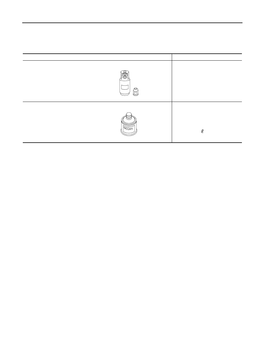
HFC-134a (R-134a) refrigerant

Container color: Light blue
Container marking: HFC-134a (R-
134a)
Fitting size: Thread size

• Large container 1/2

-16 ACME

NISSAN A/C System Oil Type S 
(DH-PS)

Type: Polyalkylene glycol oil (PAG), 
type S (DH-PS)
Application:
HFC-134a (R-134a) swash plate com-
pressors (Nissan only)

Capacity: 40 m

 (1.4 US fl oz., 1.4 

Imp fl oz.) 

S-NT196

S-NT197

Revision: 2008 October

2009 Murano

LUBRICANT

HA-25

< ON-VEHICLE MAINTENANCE >

C

D

E

F

G

H

J

K

L

M

A

B

HA

N

O

P

ON-VEHICLE MAINTENANCE

LUBRICANT

Maintenance of Lubricant Quantity

INFOID:0000000003072967

The lubricant in the compressor circulates through the system with refrigerant. Add lubricant to the compres-
sor when replacing any component or after a large refrigerant leakage is occurred. It is important to maintain
the specified amount of lubricant.
The following malfunctions may result if lubricant quantity is not maintained normally:
• Lack of lubricant: May lead to a seized compressor.
• Excessive lubricant: Inadequate cooling (thermal exchange interference)

LUBRICANT

LUBRICANT RETURN OPERATION

Adjust the lubricant quantity according to the test group shown below.

1.

CHECK LUBRICANT RETURN OPERATION

Can lubricant return operation be performed?
• A/C system works normally.
• There is no evidence of a large amount of lubricant leakage.

CAUTION:

Never perform the lubricant return operation if excessive lubricant leakage is noted.

Is it successful?

YES

>> GO TO 2.

NO

>> GO TO 3.

2.

PERFORM LUBRICANT RETURN OPERATION, PROCEEDING ACCORDING TO THE FOLLOWING

PROCEDURE

1.

Start the engine, and set to the following conditions:

-

Engine speed: Idling to 1,200 rpm

-

A/C switch: ON

-

Blower speed: Max. position

-

Temp. control: Optional [Set so that intake air temperature is 25 to 30

°

C (77 to 86

°

F).]

-

Intake position: Recirculation (REC)

2.

Perform lubricant return operation for approximately 10 minutes.

3.

Stop the engine.

>> GO TO 3.

3.

CHECK REPLACEMENT PART

Should the compressor be replaced?

YES

>> Refer to 

HA-26, "Lubricant Adjusting Procedure for Compressor Replacement"

.

NO

>> Refer to 

HA-25, "Lubricant Adjusting Procedure for Components Replacement Except Compres-

sor"

.

Lubricant Adjusting Procedure for Components Replacement Except Compressor

INFOID:0000000003072968

Add the correct amount of lubricant to the system after replacing any of the following major components.
Amount of lubricant to be added:

Name

: NISSAN A/C System Oil Type S

Revision: 2008 October

2009 Murano

HA-26

< ON-VEHICLE MAINTENANCE >

LUBRICANT

*1: No addition of lubricant is needed if the refrigerant leakage is small.

Lubricant Adjusting Procedure for Compressor Replacement

INFOID:0000000003072969

1.

Check recovery/recycling recharging equipment gauges before connecting recovery/recycling recharging
equipment to vehicle. No refrigerant pressure should be displayed. Recover refrigerant from equipment
lines if NG.

2.

Connect recovery/recycling recharging equipment to vehicle. Confirm refrigerant purity in supply tank
using recovery/recycling recharging equipment and refrigerant identifier. Refer to 

HA-14, "Working with

HFC-134a (R-134a)"

 if NG.

3.

Confirm refrigerant purity in vehicle A/C system using recovery/recycling recharging equipment and refrig-
erant identifier. If NG, refer to 

HA-14, "Working with HFC-134a (R-134a)"

.

4.

Discharge refrigerant into the recovery/recycling equipment. Measure lubricant that is discharged into the
recovery/recycling equipment.

5.

Drain the lubricant from the old (removed) compressor into a graduated container and recover the amount
of lubricant that was drained.

6.

Drain the lubricant from the new compressor into a separate. Then clean container.

7.

Measure an amount of new lubricant installed equal to the amount that was drained from the old compres-
sor. Add this lubricant to the new compressor through the suction port opening.

8.

Measure an amount of new lubricant equal to the amount that was recovered during discharging. Add this
lubricant to the new compressor through the suction port opening.

9.

Add another 5 m  (0.2 US fl oz., 0.2 Imp fl oz.) of lubricant at this time if the liquid tank also needs to be
replaced.

Part replaced

Lubricant to be added to system

Remarks

Amount of lubricant

m

 (US fl oz., Imp fl oz.)

Evaporator

75 (2.5, 2.6)

Condenser

35 (1.2, 1.2)

Liquid tank

10 (0.3, 0.4)

In case of refrigerant leakage

30 (1.0, 1.1)

Large leakage

Small leakage

 *1

Revision: 2008 October

2009 Murano

LUBRICANT

HA-27

< ON-VEHICLE MAINTENANCE >

C

D

E

F

G

H

J

K

L

M

A

B

HA

N

O

P

Do not add this 5 m  (0.2 US fl oz., 0.2 Imp fl oz.) of lubricant when replacing the compressor only.

RJIA3578E

Revision: 2008 October

2009 Murano

HA-28

< ON-VEHICLE MAINTENANCE >

REFRIGERATION SYSTEM

REFRIGERATION SYSTEM

Inspection

INFOID:0000000003072970

1.

CHECK BLOWER MOTOR OPERATION

Check blower motor operation. Refer to 

HAC-68, "Component Function Check"

 (WITHOUT 7 INCH DIS-

PLAY) or 

HAC-187, "Component Function Check"

 (WITH 7 INCH DISPLAY).

Is the inspection result normal?

YES

>> GO TO 2.

NO

>> Repair or replace the parts according to the inspection results.

2.

CHECK COMPRESSOR OPERATION

Check compressor operation. Refer to 

HAC-72, "Component Function Check"

 (WITHOUT 7 INCH DISPLAY)

or 

HAC-191, "Component Function Check"

 (WITH 7 INCH DISPLAY).

Is the inspection result normal?

YES

>> GO TO 3.

NO

>> Repair or replace the parts according to the inspection results.

3.

CHECK REFRIGERANT CYCLE PRESSURE

Connect recovery/recycling recharging equipment to the vehicle and perform the diagnosis with the gauge
pressure. Refer to 

HA-8, "Trouble Diagnosis For Unusual Pressure"

.

Is the inspection result normal?

YES

>> Perform the performance test. Refer to 

HA-28, "Performance Chart"

.

NO

>> Repair or replace the parts according to the inspection results.

Performance Chart

INFOID:0000000003072971

TEST CONDITION

Testing must be performed under the following conditions:

TEST READING

Recirculating-to-discharge Air Temperature Table

Vehicle condition

Indoors or in the shade (in a well-ventilated place)

Doors

Closed

Door windows

Open

Hood

Open

Temperature control dial/switch

Maximum cold

Mode switch

 (Ventilation) set

Intake switch

 (Recirculation) set

 Fan (blower) speed

Maximum speed set

Engine speed

Idle speed

Operate the air conditioning system for 10 minutes before taking measurements.

Inside air (Recirculating air) at blower assembly inlet

Discharge air temperature at center ventilator

°

C (

°

F)

Relative humidity

%

Air temperature

°

C (

°

F)

50 - 60

20 (68)

5.9 - 7.9 (43 - 46)

25 (77)

9.6 - 12.1 (49 - 54)

30 (86)

12.8 - 15.9 (55 - 61)

60 - 70

20 (68)

7.9 - 10.0 (46 - 50)

25 (77)

12.1 - 14.6 (54 - 58)

30 (86)

15.9 - 18.9 (61 - 66)

Revision: 2008 October

2009 Murano

REFRIGERATION SYSTEM

HA-29

< ON-VEHICLE MAINTENANCE >

C

D

E

F

G

H

J

K

L

M

A

B

HA

N

O

P

Ambient Air Temperature-to-operating Pressure Table

*1:With the cooling fan motor low-speed control

*2:With the cooling fan motor middle-speed control

*3:With the cooling fan motor high-speed control

Refrigerant Leakages

INFOID:0000000003072972

Perform a visual inspection of all refrigeration parts, fittings, hoses and components for signs of A/C lubricant
leakage, damage and corrosion. A/C lubricant leakage may indicate an area of refrigerant leakage. Allow
extra inspection time in these areas when using either an electrical leak detector or fluorescent dye leak
detector [refrigerant dye leak detection kit (SST: J-43926)].
Confirm the leakage with an electrical leak detector if dye is observed. It is possible a prior leakage was
repaired and not properly cleaned.
Do not stop when one leakage is found but continue checking for additional leakages at all system compo-
nents and connections when searching for leakages.
Move the probe along the suspected leakage area at 1 to 2 inches per second and no further than 1/4 inch
from the component when searching for refrigerant leakages using an electrical leak detector.

CAUTION:

Moving the electrical leak detector probe slower and closer to the suspected leakage area improves
the chances of finding a leakage.

Ambient air

High-pressure (Discharge side)

kPa (kg/cm

2

, psi)

Low-pressure (Suction side)

kPa (kg/cm

2

, psi)

Relative humidity

%

Air temperature

°

C (

°

F)

50 - 70

20 (68)

1,100 - 1,350

*1

(11.2 - 13.8, 159.5 - 195.8)

390 - 480

*1

(4.0 - 4.9, 56.6 - 69.6)

25 (77)

880 - 1,190

*2

(9.0 - 12.1, 127.6 - 172.6)

427 - 533

*2

(4.4 - 5.4, 61.9 - 77.3)

30 (86)

1,120 - 1,370

*2

(11.4 - 14.0, 162.4 - 198.7)

478 - 590

*2

(4.9 - 6.0, 69.3 - 85.6)

35 (95)

1,235 - 1,515

*2

(12.6 - 15.5, 179.1 - 219.7)

525 - 641

*2

(5.4 - 6.5, 76.1 - 93.0)

40 (104)

1,326 - 1,625

*3

(13.5 - 16.6, 192.3 - 235.6)

570 - 693

*3

(5.8 - 7.1, 82.7 - 100.5)

Revision: 2008 October

2009 Murano

HA-30

< ON-VEHICLE MAINTENANCE >

FLUORESCENT LEAK DETECTOR

FLUORESCENT LEAK DETECTOR

Inspection

INFOID:0000000003072973

CHECKING SYSTEM FOR LEAKAGES USING THE FLUORESCENT LEAK DETECTOR

1.

Check A/C system for leakages using the UV lamp and safety goggles (SST: J-42220) in a low sunlight
area (area without windows preferable). Illuminate all components, fittings and lines. The dye appears as
a bright green/yellow area at the point of leakage. Fluorescent dye observed at the evaporator drain open-
ing indicates an evaporator core assembly (tubes, core or expansion valve) leakage.

2.

Use an adjustable mirror or wipe the area with a waste, with the UV lamp for dye residue if the suspected
area is difficult to see.

3.

Remove any residual dye using dye cleaner (SST: J-43872) to prevent future misdiagnosis after the leak-
age is repaired.

4.

Perform a system performance check and verify the leakage repair with an approved electrical leak detec-
tor.

NOTE:
Other gases in the work area or substances on the A/C components, for example, antifreeze, windshield
washer fluid, solvents and lubricants, may falsely trigger the leak detector. Make sure the surfaces to be
checked are clean.
Clean with a dry cloth or blow off with shop air.
Do not allow the sensor tip of the detector to contact with any substance. This may also cause false readings
and may damage the detector.

DYE INJECTION

(This procedure is only necessary when recharging the system or when the compressor has seized and was
replaced.)

1.

Check A/C system static (at rest) pressure. Pressure must be at least 345 kPa (3.52 kg/cm

2

, 50 psi).

2.

Pour one bottle (1/4 ounce / 7.4 cc) of the A/C refrigerant dye into the injector tool (SST: J-41459).

3.

Connect the injector tool to the A/C low-pressure side service valve.

4.

Start the engine. Then switch A/C ON.

5.

Inject one bottle (1/4 ounce / 7.4 cc) of fluorescent dye through the low-pressure service valve using dye
injector tool (SST: J-41459) (refer to the manufacturer’s operating instructions) when the A/C is operating
(compressor is running).

6.

Disconnect the injector tool from the service valve with the engine still running.

CAUTION:

Be careful when replacing the A/C system or a component, pour the dye directly into the open sys-
tem connection and proceed with the service procedures.

7.

Operate the A/C system for a minimum of 20 minutes to mix the dye with the system oil. Depending on the
leakage size, operating conditions and location of the leakage, it may take from minutes to days for the
dye to penetrate a point of leakage and become visible.

8.

Attach a blue label if necessary.

Revision: 2008 October

2009 Murano

ELECTRICAL LEAK DETECTOR

HA-31

< ON-VEHICLE MAINTENANCE >

C

D

E

F

G

H

J

K

L

M

A

B

HA

N

O

P

ELECTRICAL LEAK DETECTOR

Inspection

INFOID:0000000003072974

PRECAUTIONS FOR HANDLING LEAK DETECTOR

Use an electrical leak detector (SST: J-41995) or equivalent when
performing a refrigerant leakage check. Ensure that the instrument is
calibrated and set properly according to the operating instructions.
The leak detector is a delicate device. Read the operating instruc-
tions and perform any specified maintenance for using the leak
detector properly.

1.

Position probe approximately 3 mm (0.12 in) away from point to
be checked.

2.

Circle each fitting completely with probe when testing.

3.

Move probe along component approximately 25 to 50 mm (1 to
2 in)/sec.

CHECKING PROCEDURE

Check that there is no refrigerant vapor, shop chemicals, or cigarette smoke in the vicinity of the vehicle to pre-
vent inaccurate or false readings. Perform the leakage test in calm area (low air/wind movement) so that the
leaking refrigerant is not dispersed.

1.

Stop the engine.

AHA281A

JSIIA1099GB

SHA706E

SHA708EA

Revision: 2008 October

2009 Murano

HA-32

< ON-VEHICLE MAINTENANCE >

ELECTRICAL LEAK DETECTOR

2.

Connect a suitable A/C manifold gauge set (SST: J-39183) to the A/C service valves.

3.

Check if the A/C refrigerant pressure is at least 345 kPa (3.52 kg/cm

2

, 50 psi) above 16

°

C (61

°

F).

Recover/evacuate and recharge the system with the specified amount of refrigerant if it is less than spec-
ification.
NOTE:
Leakages may not be detected since the system may not reach 345 kPa (3.52 kg/cm

2

, 50 psi) at temper-

atures below 16

°

C (61

°

F).

4.

Perform the leakage test from the high-pressure side (compressor discharge “a” to evaporator inlet “j”) to
the low-pressure side (evaporator drain hose “k” to shaft seal “p”). Perform a leakage check for the follow-
ing areas carefully. Clean the component to be checked and move the leakage detected probe completely
around the connection/component.

Compressor
Check the fitting of high- and low-pressure flexible hoses, relief valve and shaft seal.
Condenser
Check the fitting of condenser pipe assembly, high-pressure flexible hose and pipe.
Liquid tank
Check the fitting of condenser assembly and refrigerant pressure sensor.
Service valves
Check all around the service valves. Ensure service valve caps are secured on the service valves (to pre-
vent leakages).
NOTE:
Wipe any residue from valves to prevent any false readings by leak detector after removing A/C manifold
gauge set from service valves.
Cooling unit (Evaporator)
Turn blower fan on “High” for at least 15 seconds to dissipate any refrigerant trace in the cooling unit with
engine OFF. Wait a minimum of 10 minutes (refer to the manufacturer’s recommended procedure for the
actual wait time) before inserting the leak detector probe into the drain hose.
Keep the probe inserted for at least 10 seconds. Be careful not to contaminate the probe tip with water or
dirt that may be in the drain hose.

5.

Verify at least once by blowing compressed air into area of suspected leakage, then repeat the check as
outlined above if a leak detector detects a leakage.

6.

Do not stop when one leakage is found. Continue checking for additional leakages at all system compo-
nents.
If no leakages are found, perform steps 7 - 10.

JPIIA0458GB

Revision: 2008 October

2009 Murano

ELECTRICAL LEAK DETECTOR

HA-33

< ON-VEHICLE MAINTENANCE >

C

D

E

F

G

H

J

K

L

M

A

B

HA

N

O

P

7.

Start the engine.

8.

Set the A/C control under the following conditions.

a.

A/C switch: ON

b.

Air flow: VENT (Ventilation)

c.

Intake door position: Recirculation

d.

Temperature setting: Maximum cold

e.

Fan speed: High

9.

Run engine at 1,500 rpm for at least 2 minutes.

10. Stop the engine and perform leakage check again following

steps 4 through 6 above.
Refrigerant leakages should be checked immediately after stop-
ping the engine. Begin with the leak detector at the compressor.
The pressure on the high-pressure side drops gradually after
refrigerant circulation stops and pressure on the low-pressure
side rises gradually, as shown in the graph. Some leakages are
more easily detected when pressure is high.

11. Check recovery/recycling recharging equipment gauges before connecting recovery/recycling recharging

equipment to vehicle. No refrigerant pressure should be displayed. Recover refrigerant from equipment
lines if pressure is displayed, and then check refrigerant purity.

12. Confirm refrigerant purity in supply tank using recovery/recycling recharging equipment and refrigerant

identifier.

13. Confirm refrigerant purity in vehicle A/C system using recovery/recycling recharging equipment and refrig-

erant identifier.

14. Discharge A/C system using approved refrigerant recovery equipment. Repair the leaking fitting or com-

ponent if necessary.

15. Evacuate and recharge A/C system and perform the leakage test to confirm that there are no refrigerant

leakages.

16. Perform A/C performance test to ensure that the system works normally.

SHA839E

Revision: 2008 October

2009 Murano

HA-34

< ON-VEHICLE REPAIR >

REFRIGERATION SYSTEM

ON-VEHICLE REPAIR

REFRIGERATION SYSTEM

Exploded View

INFOID:0000000003072975

Refer to 

HA-15, "Refrigerant Connection"

.

Inspection After Installation

INFOID:0000000003072976

SETTING OF SERVICE TOOLS AND EQUIPMENT

Discharging Refrigerant

WARNING:

Never breathe A/C refrigerant and lubricant vapor or mist. Exposure may irritate eyes, nose or throat.
Remove HFC-134a (R-134a) from A/C system using certified service equipment meeting requirements
of SAE J-2210 [HFC-134a (R-134a) recycling equipment] or J-2209 [HFC-134a (R-134a) recovery equip-
ment]. Ventilate work area before resuming service if accidental system discharge occurs. Additional
health and safety information may be obtained from refrigerant and lubricant manufacturers.

1.

High-pressure pipe

2.

O-ring

3.

Condenser assembly

4.

High-pressure flexible hose

5.

Compressor

6.

Low-pressure flexible hose

7.

Low-pressure pipe

8.

Heater & cooling unit assembly

9.

Evaporator pipe assembly

10. Expansion valve

11.

Evaporator

Refer to 

GI-4, "Components"

 for symbols in the figure.

JPIIA1257GB

Revision: 2008 October

2009 Murano

REFRIGERATION SYSTEM

HA-35

< ON-VEHICLE REPAIR >

C

D

E

F

G

H

J

K

L

M

A

B

HA

N

O

P

Evacuating System and Charging Refrigerant

1.

Shut-off valve

2.

A/C service valve

3.

Recovery/Recycling Recharging 
equipment

JSIIA0238ZZ

1.

Shut-off valve

2.

A/C service valve

3.

Recovery/Recycling Recharging 
equipment

4.

Refrigerant container (HFC-134a)

5.

Weight scale (J-39650)

6.

Vacuum pump (J-39649)

7.

Manifold gauge set (J-39183)

A.

Preferred (best) method

B.

Alternative method

C.

For charging

JSIIA0239ZZ

Revision: 2008 October

2009 Murano

HA-36

< ON-VEHICLE REPAIR >

REFRIGERATION SYSTEM

*1

HA-25, "Maintenance of Lubricant 
Quantity"

*2

HA-29, "Refrigerant Leakages"

.

*3

HA-31, "Inspection"

.

*4

HA-28, "Inspection"

.

*5

HA-14, "Working with HFC-134a (R-
134a)"

.

JSIIA0607GB

Revision: 2008 October

2009 Murano

COMPRESSOR

HA-37

< ON-VEHICLE REPAIR >

C

D

E

F

G

H

J

K

L

M

A

B

HA

N

O

P

COMPRESSOR

Exploded View

INFOID:0000000003072977

Removal and Installation

INFOID:0000000003072978

REMOVAL

1.

Use refrigerant collecting equipment (for HFC-134a) to discharge the refrigerant.

2.

Remove the front under cover. Refer to 

EXT-26, "Exploded View"

3.

Remove the splash guard. Refer to 

EXT-23, "FENDER PROTECTOR : Exploded View"

4.

Remove drive belt. Refer to 

EM-13, "Exploded View"

5.

Remove the mounting bolt (A), and then disconnect the low-
pressure flexible hose (1) from the compressor. 

CAUTION:

Cap or wrap the joint of the A/C piping and compressor with
suitable material such as vinyl tape to avoid the entry of air.

6.

Remove the mounting bolt (B), and then disconnect the high-
pressure flexible hose (2) from the compressor. 

CAUTION:

Cap or wrap the joint of the A/C piping and compressor with
suitable material such as vinyl tape to avoid the entry of air.

7.

Remove the connector (A) and the harness clip (B) of the mag-
net clutch. 

1.

Compressor

Refer to 

GI-4, "Components"

 for symbols in the figure.

JPIIA1256GB

JPIIA0529ZZ

JPIIA0530ZZ

Revision: 2008 October

2009 Murano

HA-38

< ON-VEHICLE REPAIR >

COMPRESSOR

8.

Remove the mounting bolts (A), and then move the oil cooler to a position where it dose not get inhibit
work. 

9.

Remove the mounting bolts (B), and then remove the compressor (1) from the lower side of the vehicle. 

INSTALLATION

Installation is basically the reverse order of removal.

CAUTION:

• Replace O-rings with new ones. Then apply compressor oil to them when installing.
• Check for leakages when recharging refrigerant.
• Check tension of the drive belt after installing compressor. Refer to 

EM-13, "Checking"

.

Inspection

INFOID:0000000003072979

Measurement of clearance between clutch disc and pulley 

1.

Measure the clearance (B) between the pulley (1) and the cir-
cumference of the clutch disc (2) using a feeler gauge (A). 

Replace the compressor if the value is outside the standard. 

JPIIA0531ZZ

Standard

: Refer to 

HA-61, "Compressor"

.

SJIA1918E

SJIA1918E

Revision: 2008 October

2009 Murano

LOW-PRESSURE FLEXIBLE HOSE

HA-39

< ON-VEHICLE REPAIR >

C

D

E

F

G

H

J

K

L

M

A

B

HA

N

O

P

LOW-PRESSURE FLEXIBLE HOSE

Exploded View

INFOID:0000000003457520

Refer to 

HA-15, "Refrigerant Connection"

.

Removal and Installation

INFOID:0000000003072981

REMOVAL

1.

Use refrigerant collecting equipment (for HFC-134a) to discharge the refrigerant.

2.

Remove the front under cover. Refer to 

EXT-26, "Exploded View"

3.

Remove the mounting bolt (A), and then disconnect the low-
pressure flexible hose (1) from the compressor. 

CAUTION:

Cap or wrap the joint of the A/C piping and compressor with
suitable material such as vinyl tape to avoid the entry of air.

1.

High-pressure pipe

2.

O-ring

3.

Condenser assembly

4.

High-pressure flexible hose

5.

Compressor

6.

Low-pressure flexible hose

7.

Low-pressure pipe

8.

Heater & cooling unit assembly

9.

Evaporator pipe assembly

10. Expansion valve

11.

Evaporator

Refer to 

GI-4, "Components"

 for symbols in the figure.

JPIIA1257GB

JPIIA0532ZZ

Revision: 2008 October

2009 Murano


Content      ..     216      217      218      219     ..