Nissan Murano Z51 (2008 year). Manual - part 219


  Index      Manuals     Nissan Murano Z51 (2008 year) - Service and Repair Manual


Search            copyright infringement  


Content      ..     217      218      219      220     ..


Nissan Murano Z51 (2008 year). Manual - part 219


HA-40

< ON-VEHICLE REPAIR >

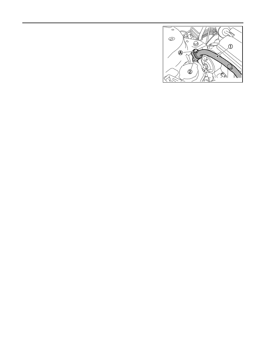
LOW-PRESSURE FLEXIBLE HOSE

4.

Remove the mounting bolt (A), and then remove the low-pres-
sure flexible hose (1) from the low-pressure pipe (2). 

CAUTION:

Cap or wrap the joint of the A/C piping with suitable mate-
rial such as vinyl tape to avoid the entry of air.

INSTALLATION

Installation is basically the reverse order of removal.

CAUTION:

• Replace O-rings with new ones. Then apply compressor oil to them when installing. 
• Check for leakages when recharging refrigerant.

JPIIA0533ZZ

Revision: 2008 October

2009 Murano

HIGH-PRESSURE FLEXIBLE HOSE

HA-41

< ON-VEHICLE REPAIR >

C

D

E

F

G

H

J

K

L

M

A

B

HA

N

O

P

HIGH-PRESSURE FLEXIBLE HOSE

Exploded View

INFOID:0000000003457524

Refer to 

HA-15, "Refrigerant Connection"

.

Removal and Installation

INFOID:0000000003072983

REMOVAL

1.

Use refrigerant collecting equipment (for HFC-134a) to discharge the refrigerant.

2.

Remove the front under cover. Refer to 

EXT-26, "Exploded View"

3.

Remove the mounting bolt (A), and then disconnect the high-
pressure flexible hose (1) from the compressor. 

CAUTION:

Cap or wrap the joint of the A/C piping and compressor with
suitable material such as vinyl tape to avoid the entry of air.

1.

High-pressure pipe

2.

O-ring

3.

Condenser assembly

4.

High-pressure flexible hose

5.

Compressor

6.

Low-pressure flexible hose

7.

Low-pressure pipe

8.

Heater & cooling unit assembly

9.

Evaporator pipe assembly

10. Expansion valve

11.

Evaporator

Refer to 

GI-4, "Components"

 for symbols in the figure.

JPIIA1257GB

JPIIA0534ZZ

Revision: 2008 October

2009 Murano

HA-42

< ON-VEHICLE REPAIR >

HIGH-PRESSURE FLEXIBLE HOSE

4.

Remove the mounting bolt (A), and then remove the high-pres-
sure flexible hose (1) from the condenser pipe assembly (2). 

CAUTION:

Cap or wrap the joint of the A/C piping with suitable mate-
rial such as vinyl tape to avoid the entry of air.

INSTALLATION

Installation is basically the reverse order of removal.

CAUTION:

• Replace O-rings with new ones. Then apply compressor oil to them when installing. 
• Check for leakages when recharging refrigerant.

JPIIA0535ZZ

Revision: 2008 October

2009 Murano

LOW-PRESSURE PIPE

HA-43

< ON-VEHICLE REPAIR >

C

D

E

F

G

H

J

K

L

M

A

B

HA

N

O

P

LOW-PRESSURE PIPE

Exploded View

INFOID:0000000003457541

Refer to 

HA-15, "Refrigerant Connection"

.

Removal and Installation

INFOID:0000000003072985

REMOVAL

1.

Use refrigerant collecting equipment (for HFC-134a) to discharge the refrigerant.

2.

Remove the mounting bolt (A), and then disconnect the low-
pressure pipe (1) from the expansion valve. 

CAUTION:

Cap or wrap the joint of the A/C piping and expansion valve
with suitable material such as vinyl tape to avoid the entry
of air.

1.

High-pressure pipe

2.

O-ring

3.

Condenser assembly

4.

High-pressure flexible hose

5.

Compressor

6.

Low-pressure flexible hose

7.

Low-pressure pipe

8.

Heater & cooling unit assembly

9.

Evaporator pipe assembly

10. Expansion valve

11.

Evaporator

Refer to 

GI-4, "Components"

 for symbols in the figure.

JPIIA1257GB

JPIIA0536ZZ

Revision: 2008 October

2009 Murano

HA-44

< ON-VEHICLE REPAIR >

LOW-PRESSURE PIPE

3.

Remove the mounting bolt (A), and then disconnect the low-
pressure flexible hose (1) from the low-pressure pipe (2). 

CAUTION:

Cap or wrap the joint of the A/C piping with suitable mate-
rial such as vinyl tape to avoid the entry of air.

4.

Move the power steering reservoir tank to a position where it dose not inhibit work.  Refer to 

ST-42,

"Exploded View"

5.

Remove the mounting nut (A) and clip (B), and then remove the
low-pressure pipe (1) together with the low-pressure pipe
bracket (2). 

INSTALLATION

Installation is basically the reverse order of removal.

CAUTION:

• Replace O-rings with new ones. Then apply compressor oil to them when installing. 
• Check for leakages when recharging refrigerant.

JPIIA0533ZZ

JPIIA0537ZZ

Revision: 2008 October

2009 Murano

HIGH-PRESSURE PIPE

HA-45

< ON-VEHICLE REPAIR >

C

D

E

F

G

H

J

K

L

M

A

B

HA

N

O

P

HIGH-PRESSURE PIPE

Exploded View

INFOID:0000000003457594

Refer to 

HA-15, "Refrigerant Connection"

.

Removal and Installation

INFOID:0000000003072987

REMOVAL

1.

Use refrigerant collecting equipment (for HFC-134a) to discharge the refrigerant.

2.

Remove the mounting bolt (A), and then disconnect the high-
pressure pipe (1) from the expansion valve. 

CAUTION:

Cap or wrap the joint of the A/C piping and expansion valve
with suitable material such as vinyl tape to avoid the entry
of air.

1.

High-pressure pipe

2.

O-ring

3.

Condenser assembly

4.

High-pressure flexible hose

5.

Compressor

6.

Low-pressure flexible hose

7.

Low-pressure pipe

8.

Heater & cooling unit assembly

9.

Evaporator pipe assembly

10. Expansion valve

11.

Evaporator

Refer to 

GI-4, "Components"

 for symbols in the figure.

JPIIA1257GB

JPIIA0538ZZ

Revision: 2008 October

2009 Murano

HA-46

< ON-VEHICLE REPAIR >

HIGH-PRESSURE PIPE

3.

Remove the mounting bolt (A), and then disconnect the high-
pressure pipe (1) from the condenser pipe assembly (2). 

CAUTION:

Cap or wrap the joint of the A/C piping with suitable mate-
rial such as vinyl tape to avoid the entry of air.

4.

Move the power steering reservoir tank to a position where it dose not inhibit work. Refer to 

ST-42,

"Exploded View"

5.

Remove the reservoir tank. Refer to 

CO-13, "Exploded View"

6.

Remove the washer tank inlet. Refer to 

WW-120, "Exploded View"

7.

Remove the clip (A), and then remove the high-pressure pipe (1). 

INSTALLATION

Installation is basically the reverse order of removal.

CAUTION:

• Replace O-rings with new ones. Then apply compressor oil to them when installing. 
• Check for leakages when recharging refrigerant.

JPIIA0539ZZ

JPIIA0540ZZ

Revision: 2008 October

2009 Murano

CONDENSER PIPE ASSEMBLY

HA-47

< ON-VEHICLE REPAIR >

C

D

E

F

G

H

J

K

L

M

A

B

HA

N

O

P

CONDENSER PIPE ASSEMBLY

Exploded View

INFOID:0000000003072988

Removal and Installation

INFOID:0000000003072989

REMOVAL

1.

Use refrigerant collecting equipment (for HFC-134a) to discharge the refrigerant.

2.

Remove the front grille. Refer to 

EXT-18, "Exploded View"

3.

Remove the mounting bolt (A), and then disconnect the high-
pressure flexible hose (2) and the high-pressure pipe (3) from
the condenser pipe assembly (1). 

CAUTION:

Cap or wrap the joint of the A/C piping with suitable mate-
rial such as vinyl tape to avoid the entry of air.

4.

Remove the mounting bolt (A), and then remove the condenser
pipe assembly (1) from the condenser. 

CAUTION:

Cap or wrap the joint of the A/C piping and condenser with
suitable material such as vinyl tape to avoid the entry of air. 

1.

Condenser pipe assembly

2.

O-ring

3.

Condenser assembly

4.

Condenser lower bracket LH

5.

Bracket

6.

Liquid tank

7.

Refrigerant pressure sensor

8.

Liquid tank bracket

9.

Condenser upper bracket LH

10. Condenser upper bracket RH

Refer to 

GI-4, "Components"

 for symbols in the figure.

JPIIA0460GB

JPIIA0541ZZ

JPIIA0542ZZ

Revision: 2008 October

2009 Murano

HA-48

< ON-VEHICLE REPAIR >

CONDENSER PIPE ASSEMBLY

INSTALLATION

Installation is basically the reverse order of removal.

CAUTION:

• Replace O-rings with new ones. Then apply compressor oil to them when installing. 
• Check for leakages when recharging refrigerant.

Revision: 2008 October

2009 Murano

CONDENSER

HA-49

< ON-VEHICLE REPAIR >

C

D

E

F

G

H

J

K

L

M

A

B

HA

N

O

P

CONDENSER

Exploded View

INFOID:0000000003458381

Removal and Installation

INFOID:0000000003072991

REMOVAL

1.

Remove the condenser pipe assembly. Refer to 

HA-47, "Exploded View"

2.

Remove the air guide upper and air guide center. Refer to 

DLK-325, "Exploded View"

 (WITH INTELLI-

GENT KEY SYSTEM) or 

DLK-543, "Exploded View"

 (WITHOUT INTELLIGENT KEY SYSTEM). 

3.

Remove hood lock assembly. Refer to 

DLK-348, "Exploded View"

 (WITH INTELLIGENT KEY SYSTEM)

or 

DLK-566, "Exploded View"

 (WITHOUT INTELLIGENT KEY SYSTEM). 

4.

Disengage the joints of the pawl (A), and then move air guide
side (LH) (1) to the position without the hindrance for work. 

1.

Condenser pipe assembly

2.

O-ring

3.

Condenser assembly

4.

Condenser lower bracket LH

5.

Bracket

6.

Liquid tank

7.

Refrigerant pressure sensor

8.

Liquid tank bracket

9.

Condenser upper bracket LH

10. Condenser upper bracket RH

Refer to 

GI-4, "Components"

 for symbols in the figure.

JPIIA0460GB

JPIIA1348ZZ

Revision: 2008 October

2009 Murano

HA-50

< ON-VEHICLE REPAIR >

CONDENSER

5.

Disconnect the refrigerant pressure sensor connector (A).

6.

Remove the tabs (A). Pull the condenser (1) in the direction
shown by the arrow, and then remove it.

CAUTION:

Be careful not to damage core surface of condenser.

INSTALLATION

Installation is basically the reverse order of removal.

CAUTION:

• Replace O-rings with new ones. Then apply compressor oil to them when installing. 
• Check for leakages when recharging refrigerant.

JPIIA0543ZZ

JPIIA1349ZZ

Revision: 2008 October

2009 Murano

LIQUID TANK

HA-51

< ON-VEHICLE REPAIR >

C

D

E

F

G

H

J

K

L

M

A

B

HA

N

O

P

LIQUID TANK

Exploded View

INFOID:0000000003458382

Removal and Installation

INFOID:0000000003072993

REMOVAL

1.

Use refrigerant collecting equipment (for HFC-134a) to discharge the refrigerant.

2.

Remove the front grille. Refer to 

EXT-18, "Exploded View"

3.

Clean liquid tank and its surrounding area. Then remove dust and rust from liquid tank.

CAUTION:

Be sure to clean carefully.

4.

Disconnect the refrigerant pressure sensor connector (A). 

1.

Condenser pipe assembly

2.

O-ring

3.

Condenser assembly

4.

Condenser lower bracket LH

5.

Bracket

6.

Liquid tank

7.

Refrigerant pressure sensor

8.

Liquid tank bracket

9.

Condenser upper bracket LH

10. Condenser upper bracket RH

Refer to 

GI-4, "Components"

 for symbols in the figure.

JPIIA0460GB

JPIIA0543ZZ

Revision: 2008 October

2009 Murano

HA-52

< ON-VEHICLE REPAIR >

LIQUID TANK

5.

Remove the mounting bolts (A), and then remove the liquid tank
(1). 

CAUTION:

Cap or wrap the joint of the A/C piping and liquid tank with
suitable material such as vinyl tape to avoid the entry of air.

INSTALLATION

 Installation is basically the reverse order of removal.

CAUTION:

• Replace O-rings with new ones. Then apply compressor oil to them when installing. 
• Check for leakages when recharging refrigerant.

JPIIA0545ZZ

Revision: 2008 October

2009 Murano

REFRIGERANT PRESSURE SENSOR

HA-53

< ON-VEHICLE REPAIR >

C

D

E

F

G

H

J

K

L

M

A

B

HA

N

O

P

REFRIGERANT PRESSURE SENSOR

Exploded View

INFOID:0000000003458383

Removal and Installation

INFOID:0000000003470196

REMOVAL

1.

Remove liquid tank. Refer to 

HA-51, "Exploded View"

.

2.

Fix the liquid tank (1) with a vise (A). Remove the refrigerant
pressure sensor (2) with a wrench (B).

CAUTION:

• Be careful not to damage liquid tank.
• Seal the refrigerant pressure sensor on liquid tank with

caps, vinyl tape, or a similar item to prevent them from
being exposed to the atmosphere. 

INSTALLATION

Installation is basically the reverse order of removal.

CAUTION:

• Replace the O-rig with a new one. Apply a coat of compressor oil to the O-ring prior to installation.
• Check for leakages when recharging refrigerant.

1.

Condenser pipe assembly

2.

O-ring

3.

Condenser assembly

4.

Condenser lower bracket LH

5.

Bracket

6.

Liquid tank

7.

Refrigerant pressure sensor

8.

Liquid tank bracket

9.

Condenser upper bracket LH

10. Condenser upper bracket RH

Refer to 

GI-4, "Components"

 for symbols in the figure.

JPIIA0460GB

JSIIA0075ZZ

Revision: 2008 October

2009 Murano

HA-54

< ON-VEHICLE REPAIR >

EVAPORATOR PIPE ASSEMBLY

EVAPORATOR PIPE ASSEMBLY

Exploded View

INFOID:0000000003457595

Refer to 

HA-15, "Refrigerant Connection"

.

Removal and Installation

INFOID:0000000003452981

REMOVAL

1.

Set the temperature (passenger side) at 18

°

C (60

°

F).

CAUTION:

The angle may be out, when installing the air mix door motor to the air mix door, unless the above
procedure is performed.

2.

Disconnect the battery cable from the negative terminal.  

3.

Use refrigerant collecting equipment (for HFC-134a) to discharge the refrigerant.

1.

High-pressure pipe

2.

O-ring

3.

Condenser assembly

4.

High-pressure flexible hose

5.

Compressor

6.

Low-pressure flexible hose

7.

Low-pressure pipe

8.

Heater & cooling unit assembly

9.

Evaporator pipe assembly

10. Expansion valve

11.

Evaporator

Refer to 

GI-4, "Components"

 for symbols in the figure.

JPIIA1257GB

Revision: 2008 October

2009 Murano

EVAPORATOR PIPE ASSEMBLY

HA-55

< ON-VEHICLE REPAIR >

C

D

E

F

G

H

J

K

L

M

A

B

HA

N

O

P

4.

Remove the mounting bolt (A), and then disconnect the low-
pressure pipe (1) and high-pressure pipe (2) from the expansion
valve. 

CAUTION:

Cap or wrap the joint of the A/C piping and expansion valve
with suitable material such as vinyl tape to avoid the entry
of air.

5.

Remove the blower unit. Refer to 

VTL-29, "Exploded View"

 (WITHOUT 7 INCH DISPLAY) or 

VTL-90,

"Exploded View"

 (WITH 7 INCH DISPLAY).

6.

Remove the mounting screws (A), and then remove the foot
duct assembly (RH) (1). 

7.

Disconnect the air mix door motor (passenger side) connector. 

8.

Remove the mounting screws (A), and then remove the heater &
cooling unit case cover (1) together with the air mix door motor
(passenger side) (2). 

9.

Remove the mounting bolts (A), and then remove the evaporator
pipe assembly (1) and the expansion valve (2) from the evapo-
rator. 

CAUTION:

Cap or wrap the joint of the A/C piping and evaporator with
suitable material such as vinyl tape to avoid the entry of air. 

JPIIA0561ZZ

JPIIA0562ZZ

JPIIA0563ZZ

JPIIA0546ZZ

Revision: 2008 October

2009 Murano


Content      ..     217      218      219      220     ..