Nissan Murano Z51 (2008 year). Manual - part 209


  Index      Manuals     Nissan Murano Z51 (2008 year) - Service and Repair Manual


Search            copyright infringement  


Content      ..     207      208      209      210     ..


Nissan Murano Z51 (2008 year). Manual - part 209


FL-8

< ON-VEHICLE REPAIR >

FUEL LEVEL SENSOR UNIT, FUEL FILTER AND FUEL PUMP ASSEMBLY

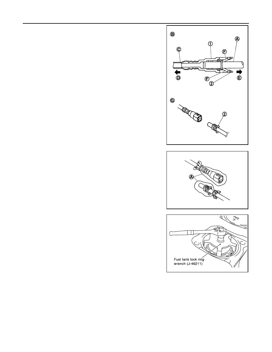
• Quick connector (1) can be disconnected when the tabs

(F) are completely depressed. Never twist it more than
necessary.

• Never use any tools to disconnected quick connector.
• Keep resin tube (C) away from heat. Be especially careful

when welding near the resin tube.

• Prevent acid liquid such as battery electrolyte, etc. from

getting on resin tube.

• Never bend or twist resin tube during installation and dis-

connection. 

• Never remove the remaining retainer (2) on hard tube (or

the equivalent) (A) except when resin tube or retainer is
replaced.

• When resin tube or hard tube (or the equivalent) is

replaced, also replace retainer with new one. 

• To keep the connecting portion clean and to avoid dam-

age and foreign materials, cover them completely with
plastic bags (A) or something similar.      

8.

Remove retainer for main fuel level sensor unit, fuel filter and
fuel pump assembly and sub fuel level sensor unit with fuel tank
lock ring wrench (SST) by turning counterclockwise.

9.

Remove main fuel level sensor unit, fuel filter and fuel pump assembly, and sub fuel level sensor unit.

B

: Connection (cross-section)

D

: To under floor fuel line

E

: To fuel tank

G

: Disconnection

Retainer color: Green

JPBIA0130ZZ

JPBIA0135ZZ

SBIA0411E

Revision: 2008 October

2009 Murano

FUEL LEVEL SENSOR UNIT, FUEL FILTER AND FUEL PUMP ASSEMBLY

FL-9

< ON-VEHICLE REPAIR >

C

D

E

F

G

H

I

J

K

L

M

A

FL

N

P

O

• Raise main fuel level sensor unit, fuel filter and fuel pump

assembly, and disconnect fuel hose connector (push in tabs
and pull out) and sub fuel level sensor unit harness connector.

• Raise and release sub fuel level sensor unit to remove.

INSTALLATION

Note to the following, and install in the reverse order of removal.

Main and Sub Fuel Level Sensor Unit

1.

Install new seal packing to fuel tank without any twist.

2.

Connect fuel hose connector (push in until it stops) and sub fuel
level sensor unit harness connector.
NOTE:
When installing fuel hose connector insert them fully until a click
sound of full stopper engagement is heard.

3.

Align the direction mark on main fuel level sensor unit, fuel filter
and fuel pump assembly and sub fuel level sensor unit with that
on fuel tank as shown in the figure, and install them to fuel tank.

CAUTION:

• Never allow seal packing to drop.
• Never bend float arm during installing.

4.

Install retainer for main fuel level sensor unit, fuel filter and fuel
pump assembly and sub fuel level sensor unit with fuel tank lock
ring wrench (SST) by turning clockwise.

CAUTION:

Install retainer horizontally.

Quick Connector

Connect quick connector as follows:

1.

Check the connection for damage or any foreign materials.

2.

Align the connector with the tube, then insert the connector straight into the tube until a click sound is
heard.

3.

After connecting, check that the connection is secure by following method.

SBIA0396E

SBIA0398E

SBIA0397E

SBIA0411E

Revision: 2008 October

2009 Murano

FL-10

< ON-VEHICLE REPAIR >

FUEL LEVEL SENSOR UNIT, FUEL FILTER AND FUEL PUMP ASSEMBLY

• Pull (A) the tube and the connector to check they are securely

connected.

• Visually confirm that the two retainer tabs are connected to the

connector.

Disassembly and Assembly

INFOID:0000000003351696

DISASSEMBLY

Fuel level sensor unit, fuel filter and fuel pump assembly side

1.

Disconnect harness connector.

2.

Remove fuel level sensor unit according to the following procedure.

a.

Push the pawl of fuel level sensor unit (1) mounting area with an
L-shaped iron rod or an equivalent to unlock.

CAUTION:

Be careful not to damage it.

b.

With the fuel level sensor unit unlocked, slide it in the direction
shown by the arrow (

).

Sub fuel level sensor unit assembly side

1.

Remove sub fuel level sensor unit according to the following procedure.

a.

Push the pawl of sub fuel level sensor unit (1) mounting area
with an L-shaped iron rod or an equivalent to unlock.

CAUTION:

Be careful not to damage it.

b.

With the sub fuel level sensor unit unlocked, slide it in the direc-
tion shown by the arrow (

).

ASSEMBLY

Install fuel level sensor unit and sub fuel level sensor unit according to the following procedure.
• Insert fuel level sensor unit and sub fuel level sensor unit all the way to the end until a “click” touch and

sound can be recognized.

• Pull fuel level sensor unit and sub fuel level sensor unit in the removal direction to ensure that they do not

become detached.

Inspection

INFOID:0000000003304314

INSPECTION AFTER INSTALLATION

Use the following procedure to check for fuel leakage.
1.

Turn ignition switch “ON” (with engine stopped), then check connections for leakage by applying fuel pres-
sure to fuel piping.

JPBIA0140ZZ

PBIC4900J

PBIC4899J

Revision: 2008 October

2009 Murano

FUEL LEVEL SENSOR UNIT, FUEL FILTER AND FUEL PUMP ASSEMBLY

FL-11

< ON-VEHICLE REPAIR >

C

D

E

F

G

H

I

J

K

L

M

A

FL

N

P

O

2.

Start engine and let it idle and check there are no fuel leakage at the fuel system connections.

Revision: 2008 October

2009 Murano

FL-12

< ON-VEHICLE REPAIR >

FUEL TANK

FUEL TANK

Exploded View

INFOID:0000000003304315

• In regard to the notation of torque in the figure, (A) shows an ISO standard, (B) shows a conventional stan-

dard.

Removal and Installation

INFOID:0000000003304316

WARNING:

Be sure to read “General Precautions” when working on the fuel system. Refer to 

FL-2, "General Pre-

cautions"

.

REMOVAL

• Drain fuel from fuel tank if necessary. Refer to 

FL-6, "Removal and Installation"

.

• Perform work on level place.

1.

Perform steps 2 to 7 of “REMOVAL” in “ FUEL LEVEL SENSOR UNIT, FUEL FILTER AND FUEL PUMP
ASSEMBLY” on main and sub fuel level sensor units. Refer to 

FL-6, "Removal and Installation"

.

2.

Remove center muffler. Refer to 

EX-5, "Exploded View"

.

1.

Clamp

2.

EVAP/Vent line hose

3.

Fuel tank

4.

Fuel tank mounting band (RH)

5.

Fuel tank protector

6.

Fuel tank protector (RH)

7.

Fuel tank protector (LH)

8.

Fuel tank mounting band (LH)

9.

Clamp

10. Clamp

11.

Fuel filler hose

12. EVAP (Recirculation) hose

13. Clamp

14.

Fuel filler tube

15. Grommet

16. Fuel filler cap

A.

The measurement of hexagonal 
width across flat: 16 mm (0.63 in)

B.

The measurement of hexagonal 
width across flat: 17 mm (0.67 in)

C.

AWD 20 inch tire models (up to VIN 
No. JN8AZ18W79W125941)

Refer to 

GI-4, "Components"

 for to symbols in the figure.

JPBIA2661GB

Revision: 2008 October

2009 Murano

FUEL TANK

FL-13

< ON-VEHICLE REPAIR >

C

D

E

F

G

H

I

J

K

L

M

A

FL

N

P

O

3.

Remove propeller shaft. Refer to 

DLN-80, "Exploded View"

. (AWD models)

4.

Remove parking rear brake cables. Refer to 

PB-6, "Exploded View"

.

5.

Remove rear suspension member assembly. Refer to 

RSU-18, "Exploded View"

. (AWD models)

NOTE:
For this service, drive shaft, final drive, and rear suspension member are required not to be separate one
another during removal.

6.

Remove fuel tank protectors.

7.

Disconnect fuel filler hose (1), EVAP/Vent line hose (3), and
EVAP (Recirculation) hose (2) from the side other than the fuel
tank side.

8.

Support the lower part of fuel tank (1) with transmission jack (A).

CAUTION:

Support the position that fuel tank mounting bands never
engage.

9.

Remove fuel tank mounting bands.

10. Supporting with hands, descend transmission jack carefully, and remove fuel tank.

CAUTION:

• Check that all connection points have been disconnected.
• Confirm there is no interference with vehicle.

11. Remove fuel filler tube if necessary.

INSTALLATION

Note the following, and install in the reverse order of removal.
• Surely clamp fuel hoses and insert hose to the length below.

• Be sure hose clamp is not placed on swelled area of fuel tube.
• Tighten the clamp hand with the top mark (A) until the mark is on

the bolt head flange.

: Vehicle front

JPBIA1696ZZ

JPBIA0145ZZ

Fuel filler hose 

: 35 mm (1.38 in)

The other hoses

: 25 mm (0.98 in)

JPBIA0146ZZ

Revision: 2008 October

2009 Murano

FL-14

< ON-VEHICLE REPAIR >

FUEL TANK

• To connect quick connector, refer to 

FL-6, "Removal and Installation"

.

Inspection

INFOID:0000000003304317

INSPECTION AFTER INSTALLATION

Use the following procedure to check for fuel leakage.

1.

Turn ignition switch “ON” (with engine stopped), and check connections for leakage by applying fuel pres-
sure to fuel piping.

2.

Start engine and rev it up and check there are no fuel leakage at the fuel system tube and hose connec-
tions.

• After removing/installing rear suspension assembly, check to adjust wheel alignment and then, adjust neutral

position of steering angle sensor. Refer to 

RSU-6, "Inspection"

 and 

BRC-9, "ADJUSTMENT OF STEERING

ANGLE SENSOR NEUTRAL POSITION : Special Repair Requirement"

.

Revision: 2008 October

2009 Murano

SERVICE DATA AND SPECIFICATIONS (SDS)

FL-15

< SERVICE DATA AND SPECIFICATIONS (SDS) 

C

D

E

F

G

H

I

J

K

L

M

A

FL

N

P

O

SERVICE DATA AND SPECIFICATIONS (SDS)

SERVICE DATA AND SPECIFICATIONS (SDS)

Fuel Tank

INFOID:0000000003304321

Standard and Limit

Fuel tank capacity

Approx. 82   (21-5/8 US gal, 18 Imp gal)

Fuel recommendation

Refer to 

GI-30

Revision: 2008 October

2009 Murano

FSU-1

SUSPENSION

C

D

F

G

H

I

J

K

L

M

SECTION 

FSU

A

B

FSU

N

O

P

CONTENTS

FRONT SUSPENSION

SYMPTOM DIAGNOSIS  ...............................

3

NOISE, VIBRATION AND HARSHNESS 
(NVH) TROUBLESHOOTING  .............................

3

NVH Troubleshooting Chart  ......................................

3

PRECAUTION ...............................................

4

PRECAUTIONS ...................................................

4

FOR USA AND CANADA ............................................

4

FOR USA AND CANADA : Precaution for Supple-
mental Restraint System (SRS) "AIR BAG" and 
"SEAT BELT PRE-TENSIONER" ............................
..

4

FOR USA AND CANADA : Precaution Necessary 
for Steering Wheel Rotation after Battery Discon-
nect .........................................................................
..

4

FOR USA AND CANADA : Precaution for Proce-
dure without Cowl Top Cover ..................................
..

5

FOR USA AND CANADA : Precautions for Sus-
pension ....................................................................
..

5

FOR MEXICO  ..............................................................

5

FOR MEXICO : Precaution for Supplemental Re-
straint System (SRS) "AIR BAG" and "SEAT BELT 
PRE-TENSIONER" .................................................
..

5

FOR MEXICO : Precaution Necessary for Steer-
ing Wheel Rotation after Battery Disconnect  ..........
..

5

FOR MEXICO : Precaution for Procedure without 
Cowl Top Cover  ......................................................
..

6

FOR MEXICO : Precautions for Suspension  ............

6

PREPARATION ............................................

7

PREPARATION ...................................................

7

Special Service Tool  .................................................

7

Commercial Service Tool  ..........................................

7

ON-VEHICLE MAINTENANCE .....................

8

FRONT SUSPENSION ASSEMBLY  ...................

8

Inspection ..................................................................

8

WHEEL ALIGNMENT  ........................................

9

Inspection .................................................................

9

ON-VEHICLE REPAIR .................................

10

FRONT COIL SPRING AND STRUT  ................

10

Exploded View .........................................................

10

Removal and Installation  .........................................

10

Disassembly and Assembly .....................................

11

Inspection ................................................................

12

Disposal ...................................................................

12

TRANSVERSE LINK .........................................

13

Exploded View .........................................................

13

Removal and Installation  .........................................

13

Inspection ................................................................

13

FRONT STABILIZER  ........................................

15

Exploded View .........................................................

15

Removal and Installation  .........................................

15

Inspection ................................................................

16

REMOVAL AND INSTALLATION  ...............

17

FRONT SUSPENSION MEMBER .....................

17

Exploded View .........................................................

17

Removal and Installation  .........................................

17

Inspection ................................................................

17

SERVICE DATA AND SPECIFICATIONS 
(SDS) ............................................................

19

SERVICE DATA AND SPECIFICATIONS 
(SDS) .................................................................

19

APPLICATION NOTICE .............................................

19

APPLICATION NOTICE : How to Check Vehicle 
Type .........................................................................

19

TYPE A .......................................................................

19

TYPE A : Wheel Alignment ......................................

19

TYPE A : Ball Joint  ..................................................

19

Revision: 2008 October

2009 Murano

NOISE, VIBRATION AND HARSHNESS (NVH) TROUBLESHOOTING

FSU-3

< SYMPTOM DIAGNOSIS >

C

D

F

G

H

I

J

K

L

M

A

B

FSU

N

O

P

SYMPTOM DIAGNOSIS

NOISE, VIBRATION AND HARSHNESS (NVH) TROUBLESHOOTING

NVH Troubleshooting Chart

INFOID:0000000003451884

Use chart below to find the cause of the symptom. If necessary, repair or replace these parts.

×

: Applicable

Reference page

FS

U-

1

0

FS

U-

13

FSU-1

5

FSU-17

FSU-12

FS

U-

1

0

FS

U-

13

FSU-1

5

FSU-17

FSU-9

FSU-16

NVH in DLN section

NVH in DLN section

NV

H in

 F

A

X

 an

FSU s

e

c

tio

ns

NVH in WT 

section

NVH in WT 

section

NVH in F

AX section

NVH in BR 

section

NVH in S

T

 section

Possible cause and SUSPECTED PARTS

Im

p

rop

er i

ns

ta

lla

ti

o

n,

 lo

os

en

es

s

Sh

oc

k ab

so

rbe

de

form

at

io

n, dam

a

ge or 

d

e

flec

ti

on

Bu

sh

in

g o

r m

o

u

n

ti

ng

 de

teri

ora

tio

n

Part

s interf

erence

S

p

rin

g

 f

a

ti

gu

e

Su

sp

en

si

on

 lo

os

en

es

s

In

co

rrec

t wh

ee

l a

lig

nm

en

t

S

tab

ili

ze

r ba

r fa

tig

u

e

PROPELLER S

H

AFT (A

W

D

)

DIFF

ERENTIAL (A

WD)

FRONT A

X

LE 

AND FRONT SUSPE

NSION

TI

RE

ROAD   

WHEEL

DRIVE SHAFT

BRAKE

STE

E

RING

Symptom

FRONT SUSPENSION

Noise

×

×

×

×

×

×

×

×

×

×

×

×

×

×

Shake

×

×

×

×

×

×

×

×

×

×

×

×

Vibration

×

×

×

×

×

×

×

×

×

×

Shimmy

×

×

×

×

×

×

×

×

×

×

Judder 

×

×

×

×

×

×

×

×

Poor quality ride or 
handling

×

×

×

×

×

×

×

×

×

×

Revision: 2008 October

2009 Murano

FSU-4

< PRECAUTION >

PRECAUTIONS

PRECAUTION

PRECAUTIONS

FOR USA AND CANADA

FOR USA AND CANADA : Precaution for Supplemental Restraint System (SRS) "AIR 
BAG" and "SEAT BELT PRE-TENSIONER"

INFOID:0000000004755091

The Supplemental Restraint System such as “AIR BAG” and “SEAT BELT PRE-TENSIONER”, used along
with a front seat belt, helps to reduce the risk or severity of injury to the driver and front passenger for certain
types of collision. This system includes seat belt switch inputs and dual stage front air bag modules. The SRS
system uses the seat belt switches to determine the front air bag deployment, and may only deploy one front
air bag, depending on the severity of a collision and whether the front occupants are belted or unbelted.
Information necessary to service the system safely is included in the “SRS AIRBAG” and “SEAT BELT” of this
Service Manual.

WARNING:

• To avoid rendering the SRS inoperative, which could increase the risk of personal injury or death in

the event of a collision which would result in air bag inflation, all maintenance must be performed by
an authorized NISSAN/INFINITI dealer.

• Improper maintenance, including incorrect removal and installation of the SRS, can lead to personal

injury caused by unintentional activation of the system. For removal of Spiral Cable and Air Bag
Module, see the “SRS AIRBAG”.

• Never use electrical test equipment on any circuit related to the SRS unless instructed to in this Ser-

vice Manual. SRS wiring harnesses can be identified by yellow and/or orange harnesses or harness
connectors.

PRECAUTIONS WHEN USING POWER TOOLS (AIR OR ELECTRIC) AND HAMMERS

When working near the Airbag Diagnosis Sensor Unit or other Airbag System sensors while ignition switch is
ON or engine is running, never use air or electric power tools or strike near the sensor(s) with a hammer.
Heavy vibration may activate the sensor(s), deploy the airbag(s), possibly cause serious injury.
When using air or electric power tools or hammers, always turn OFF ignition switch, disconnect the battery,
and wait 3 minutes or more before performing any service.

FOR USA AND CANADA : Precaution Necessary for Steering Wheel Rotation after 
Battery Disconnect

INFOID:0000000004755093

NOTE:
• Before removing and installing any control units, first turn the push-button ignition switch to the LOCK posi-

tion, then disconnect both battery cables.

• After finishing work, confirm that all control unit connectors are connected properly, then re-connect both

battery cables.

• Always use CONSULT-III to perform self-diagnosis as a part of each function inspection after finishing work.

If a DTC is detected, perform trouble diagnosis according to self-diagnosis results.

This vehicle is equipped with a push-button ignition switch and a steering lock unit.
If the battery is disconnected or discharged, the steering wheel will lock and cannot be turned.
If turning the steering wheel is required with the battery disconnected or discharged, follow the procedure
below before starting the repair operation.

OPERATION PROCEDURE

1.

Connect both battery cables.
NOTE:
Supply power using jumper cables if battery is discharged.

2.

Turn the push-button ignition switch to ACC position.
(At this time, the steering lock will be released.)

3.

Disconnect both battery cables. The steering lock will remain released with both battery cables discon-
nected and the steering wheel can be turned.

4.

Perform the necessary repair operation.

Revision: 2008 October

2009 Murano

PRECAUTIONS

FSU-5

< PRECAUTION >

C

D

F

G

H

I

J

K

L

M

A

B

FSU

N

O

P

5.

When the repair work is completed, re-connect both battery cables. With the brake pedal released, turn
the push-button ignition switch from ACC position to ON position, then to LOCK position. (The steering
wheel will lock when the push-button ignition switch is turned to LOCK position.)

6.

Perform self-diagnosis check of all control units using CONSULT-III.

FOR USA AND CANADA : Precaution for Procedure without Cowl Top Cover

INFOID:0000000004755095

When performing the procedure after removing cowl top cover, cover
the lower end of windshield with urethane, etc.

FOR USA AND CANADA : Precautions for Suspension

INFOID:0000000003451888

• When installing rubber bushings, the final tightening must be carried out under unladen conditions with tires

on ground. Spilled oil might shorten the life of rubber bushings. Be sure to wipe off any spilled oil.

- Unladen conditions mean that fuel, engine coolant and lubricant are full. Spare tire, jack, hand tools and

mats are in designated positions.

• After servicing suspension parts, be sure to check wheel alignment.
• Self-lock nuts are not reusable. Always use new ones when installing. Since new self-lock nuts are pre-oiled,

tighten as they are. 

FOR MEXICO

FOR MEXICO : Precaution for Supplemental Restraint System (SRS) "AIR BAG" and 
"SEAT BELT PRE-TENSIONER"

INFOID:0000000004755092

The Supplemental Restraint System such as “AIR BAG” and “SEAT BELT PRE-TENSIONER”, used along
with a front seat belt, helps to reduce the risk or severity of injury to the driver and front passenger for certain
types of collision. This system includes seat belt switch inputs and dual stage front air bag modules. The SRS
system uses the seat belt switches to determine the front air bag deployment, and may only deploy one front
air bag, depending on the severity of a collision and whether the front occupants are belted or unbelted.
Information necessary to service the system safely is included in the “SRS AIRBAG” and “SEAT BELT” of this
Service Manual.

WARNING:

• To avoid rendering the SRS inoperative, which could increase the risk of personal injury or death in

the event of a collision which would result in air bag inflation, all maintenance must be performed by
an authorized NISSAN/INFINITI dealer.

• Improper maintenance, including incorrect removal and installation of the SRS, can lead to personal

injury caused by unintentional activation of the system. For removal of Spiral Cable and Air Bag
Module, see the “SRS AIRBAG”.

• Never use electrical test equipment on any circuit related to the SRS unless instructed to in this Ser-

vice Manual. SRS wiring harnesses can be identified by yellow and/or orange harnesses or harness
connectors.

PRECAUTIONS WHEN USING POWER TOOLS (AIR OR ELECTRIC) AND HAMMERS

When working near the Airbag Diagnosis Sensor Unit or other Airbag System sensors while ignition switch is
ON or engine is running, never use air or electric power tools or strike near the sensor(s) with a hammer.
Heavy vibration may activate the sensor(s), deploy the airbag(s), possibly cause serious injury.
When using air or electric power tools or hammers, always turn OFF ignition switch, disconnect the battery,
and wait 3 minutes or more before performing any service.

FOR MEXICO : Precaution Necessary for Steering Wheel Rotation after Battery Dis-

PIIB3706J

Revision: 2008 October

2009 Murano

FSU-6

< PRECAUTION >

PRECAUTIONS

connect

INFOID:0000000004755094

NOTE:
• Before removing and installing any control units, first turn the push-button ignition switch to the LOCK posi-

tion, then disconnect both battery cables.

• After finishing work, confirm that all control unit connectors are connected properly, then re-connect both

battery cables.

• Always use CONSULT-III to perform self-diagnosis as a part of each function inspection after finishing work.

If a DTC is detected, perform trouble diagnosis according to self-diagnosis results.

This vehicle is equipped with a push-button ignition switch and a steering lock unit.
If the battery is disconnected or discharged, the steering wheel will lock and cannot be turned.
If turning the steering wheel is required with the battery disconnected or discharged, follow the procedure
below before starting the repair operation.

OPERATION PROCEDURE

1.

Connect both battery cables.
NOTE:
Supply power using jumper cables if battery is discharged.

2.

Turn the push-button ignition switch to ACC position.
(At this time, the steering lock will be released.)

3.

Disconnect both battery cables. The steering lock will remain released with both battery cables discon-
nected and the steering wheel can be turned.

4.

Perform the necessary repair operation.

5.

When the repair work is completed, re-connect both battery cables. With the brake pedal released, turn
the push-button ignition switch from ACC position to ON position, then to LOCK position. (The steering
wheel will lock when the push-button ignition switch is turned to LOCK position.)

6.

Perform self-diagnosis check of all control units using CONSULT-III.

FOR MEXICO : Precaution for Procedure without Cowl Top Cover

INFOID:0000000004755096

When performing the procedure after removing cowl top cover, cover
the lower end of windshield with urethane, etc.

FOR MEXICO : Precautions for Suspension

INFOID:0000000004755090

• When installing rubber bushings, the final tightening must be carried out under unladen conditions with tires

on ground. Spilled oil might shorten the life of rubber bushings. Be sure to wipe off any spilled oil.

- Unladen conditions mean that fuel, engine coolant and lubricant are full. Spare tire, jack, hand tools and

mats are in designated positions.

• After servicing suspension parts, be sure to check wheel alignment.
• Self-lock nuts are not reusable. Always use new ones when installing. Since new self-lock nuts are pre-oiled,

tighten as they are. 

PIIB3706J

Revision: 2008 October

2009 Murano

PREPARATION

FSU-7

< PREPARATION >

C

D

F

G

H

I

J

K

L

M

A

B

FSU

N

O

P

PREPARATION

PREPARATION

Special Service Tool

INFOID:0000000003451893

The actual shapes of Kent-More tools may differ from those of special service tools illustrated here.

Commercial Service Tool

INFOID:0000000003451894

Tool number
(Kent-More No.)
Tool name

Description

ST35652000
(

)

Strut attachment

Disassembling and assembling strut 

ZZA0807D

Tool name

Description

Spring compressor

Removing and installing coil spring

Power tool

Loosening bolts and nuts

S-NT717

PBIC0190E

Revision: 2008 October

2009 Murano

FSU-8

< ON-VEHICLE MAINTENANCE >

FRONT SUSPENSION ASSEMBLY

ON-VEHICLE MAINTENANCE

FRONT SUSPENSION ASSEMBLY

Inspection

INFOID:0000000003451895

MOUNTING INSPECTION

Make sure the mounting conditions (looseness, backlash) of each component and component conditions
(wear, damage) are normal.

BALL JOINT AXIAL END PLAY

1.

Set front wheels in a straight-ahead position.

2.

Measure axial end play by prying it up/down with iron bar or equivalent between transverse link and steer-
ing knuckle.
NOTE:
About TYPE A and TYPE B, refer to 

FSU-19, "APPLICATION NOTICE : How to Check Vehicle Type"

.

CAUTION:

• Never depress brake pedal when measuring.
• Never perform with tires on level ground.
• Be careful not to damage ball joint boot. Never damage the installation position by applying

excessive force.

STRUT ASSEMBLY

Check for oil leakage, damage, and replace if necessary.

Standard

Axial end play

: Refer to 

FSU-19, "TYPE A : Ball Joint"

FSU-21, "TYPE B : Ball 

Joint"

.

Revision: 2008 October

2009 Murano


Content      ..     207      208      209      210     ..