содержание .. 804 805 806 807 ..
Nissan Murano. Manual - part 806
HA-60
< REMOVAL AND INSTALLATION >
EXPANSION VALVE
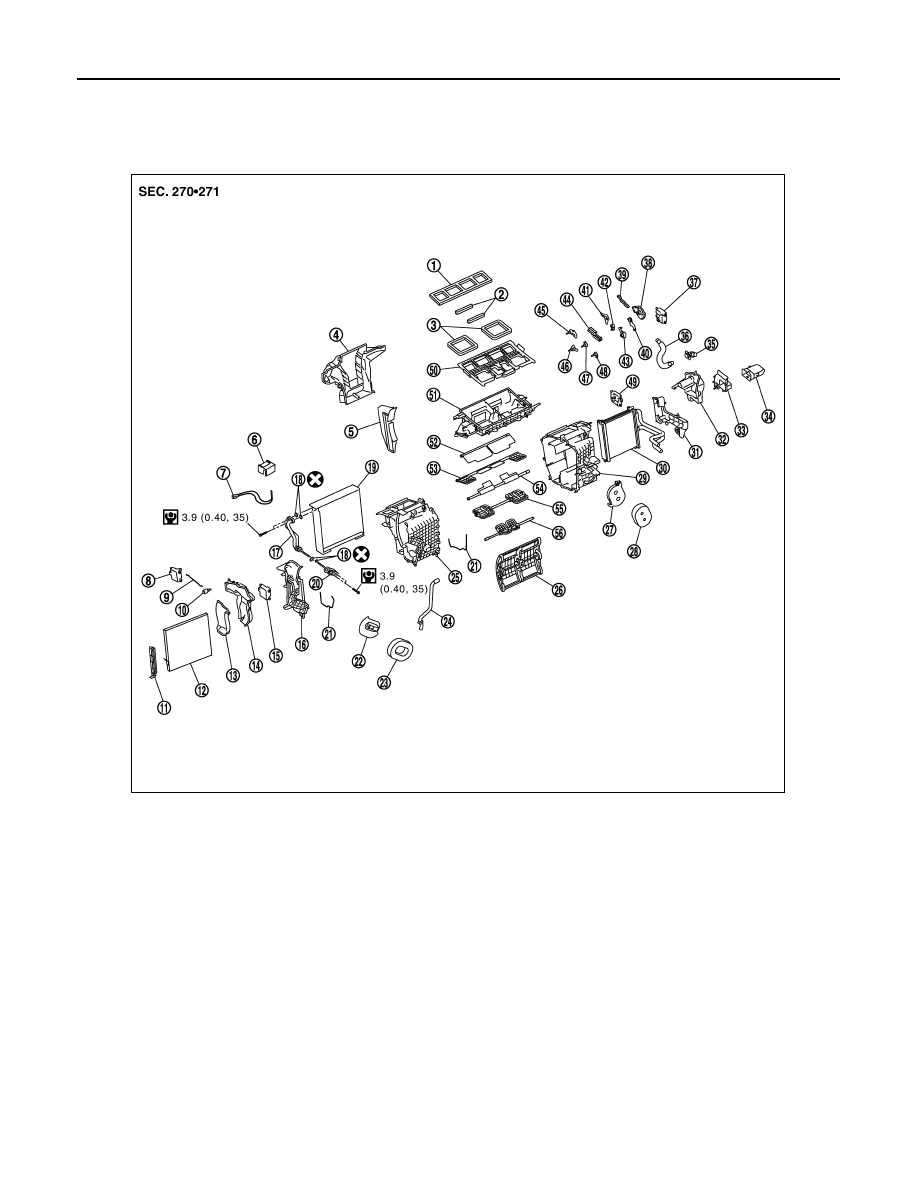
EXPANSION VALVE
Exploded View
INFOID:0000000009718662
1.
Ventilator seal
2.
Upper ventilator seal
3.
Defroster seal
4.
Adapter case
5.
Center case
6.
Intake sensor bracket
7.
Intake sensor
8.
Upper ventilator door motor
9.
Upper ventilator door rod
10. Upper ventilator door lever
11.
Filter cover
12.
In-cabin microfilter
13. Foot duct 1 RH
14.
Foot duct 2 RH
15.
Air mix door motor (Passenger side)
16. Heater & cooling unit case cover
17.
Evaporator pipe assembly
18.
O-ring
19. Evaporator
20.
Expansion valve
21.
Case packing
22. Grommet
23.
Cooler pipe grommet
24.
Drain hose
25. Heater & cooling unit case RH
26.
Air mix door (Slide door)
27.
Heater pipe support
28. Heater pipe grommet
29.
Heater & cooling unit case LH
30.
Heater core
31. Heater pipe cover
32.
Foot duct 2 LH
33.
Foot duct 1 LH
34. Heater duct
35.
Aspirator
36.
Aspirator hose
37. Mode door motor
38.
Main link
39.
Rod link
40. Max. cool door link
41.
Ventilator door link
42.
Foot door link
43. Mode door lever
44.
Defroster door link
45.
Ventilator door lever
46. Foot door lever
47.
Defroster door lever
48.
Max. cool door lever
JPIIA0454GB