содержание .. 619 620 621 622 ..
Nissan Murano. Manual - part 621
EM-58
< REMOVAL AND INSTALLATION >
TIMING CHAIN
Removal and Installation
INFOID:0000000009717983
REMOVAL
1.
Drain engine oil. Refer to
.
2.
Drain engine coolant from inside engine. Refer to
3.
Remove intake manifold collector. Refer to
4.
Remove rocker covers (bank 1 and bank 2). Refer to
5.
Remove oil pans (lower and upper) and oil strainer. Refer to
.
6.
Remove drive belt, idler pulleys and bracket. Refer to
EM-17, "Removal and Installation"
7.
Remove power steering oil pump with piping connected, and temporarily secure it to aside. Refer to
8.
Separate engine harness removing their brackets from front timing chain case.
9.
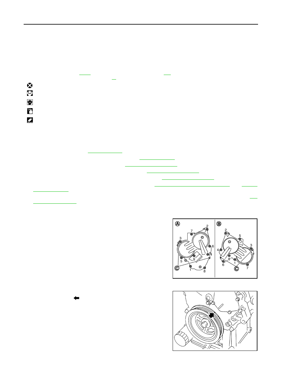
Remove valve timing control covers.
• Loosen mounting bolts in the reverse order as shown in the
figure.
CAUTION:
Shaft is internally jointed with camshaft sprocket (INT) cen-
ter hole. When removing, keep it horizontal until it is com-
pletely disconnected.
10. Obtain No. 1 cylinder at TDC of its compression stroke as follows:
a.
Rotate crankshaft pulley clockwise to align timing mark (grooved
line without color) (
) with timing indicator.
19.
Valve timing control cover gasket
(bank 1)
20. Valve timing control cover (bank 1) 21.
Intake valve timing control solenoid valve
(bank 1)
22. Seal ring
23. Water pump cover
24.
Front oil seal
25. Crankshaft pulley
26. Crankshaft pulley bolt
27.
Intake valve timing control solenoid valve
(bank 2)
28. Valve timing control cover (bank 2)
29.
Valve timing control cover gasket
(bank 2)
A.
Comply with the installation procedure
when tightening.Refer to
B.
Comply with the installation proce-
dure when tightening.Refer to
: Always replace after every disassembly.
: N·m (kg-m, ft-lb)
: N·m (kg-m, in-lb)
: Should be lubricated with oil.
: Sealing point
A
: Bank 1
B
: Bank 2
C
: Dowel pin hole
JPBIA1639ZZ
SEM727G