Nissan Murano. Manual - part 622


  Главная      Nissan     Nissan Murano (2014 year) - Service Manual


поиск по сайту            


содержание   ..  620  621  622  623   ..


Nissan Murano. Manual - part 622


EM-62

< REMOVAL AND INSTALLATION >

TIMING CHAIN

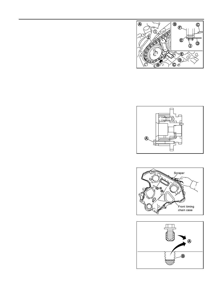
• Insert 0.5 mm (0.020 in) thick metal or resin plate between tim-

ing chain and timing chain tensioner plunger (guide) (E).
Remove timing chain (secondary) (2) together with camshaft
sprockets with timing chain loose from guide groove.

CAUTION:

Be careful of plunger coming-off when removing timing chain (secondary). This is because
plunger of timing chain tensioner (secondary) moves during operation, leading to coming-off of
fixed stopper pin. 
NOTE:
• Camshaft sprocket (INT) is two-for-one structure of sprockets for timing chain (primary) and for timing

chain (secondary).

• Figure is shown as an example of bank 1.

• When handling camshaft sprocket (INT), be careful of the fol-

lowing caution:

CAUTION:

• Handle carefully to avoid any shock to camshaft

sprocket.

• Never disassemble. [Never loosen bolts (A) as shown in

the figure].

20. Remove timing chain tensioners (secondary) from cylinder head as follows, if necessary.

• Remove timing chain tensioners (secondary) with a stopper pin attached.

21. Use a scraper to remove all traces of old liquid gasket from front

timing chain case, and opposite mating surfaces.

• Remove old liquid gasket from bolt hole (B) and thread.

1

: Timing chain tensioner (secondary)

A

:  Bank  1

B

:  View  B

C

: Stopper pin

D

:  Plate

F

: Timing chain tensioner (body)

JPBIA2527ZZ

PBIC2980E

SEM737G

A

: Remove sticking old liquid gasket 

JPBIA0051ZZ

TIMING CHAIN

EM-63

< REMOVAL AND INSTALLATION >

C

D

E

F

G

H

I

J

K

L

M

A

EM

N

P

O

22. Use a scraper to remove all traces of old liquid gasket from

water pump cover.

INSTALLATION

CAUTION:

Do not reuse O-rings.
NOTE:
The below figure shows the relationship between the mating mark on each timing chain and that on the corre-
sponding sprocket, with the components installed.

1.

Install timing chain tensioners (secondary) to cylinder head as follows if removed. Refer to 

EM-98,

"Exploded View"

.

• Install timing chain tensioners (secondary) with a stopper pin attached and new O-ring.

SEM926E

1.

Internal chain guide

2.

Camshaft sprocket (INT)

3.

Timing chain (secondary)

4.

Camshaft sprocket (EXH)

5.

Timing chain tensioner (primary)

6.

Slack guide

7.

Timing chain (primary)

8.

Crankshaft sprocket

9.

Water pump

10. Tension guide

11.

Timing chain tensioner (secondary)

12. Crankshaft key

A.

Mating mark

B.

Mating mark (pink link)

C.

Mating mark (punched)

D.

Mating mark (orange)

E.

Mating mark (notched)

JPBIA1716GB

EM-64

< REMOVAL AND INSTALLATION >

TIMING CHAIN

2.

Check that dowel pin (A) and crankshaft key (1) are located as
shown in the figure. (No. 1 cylinder at compression TDC)
NOTE:
Though camshaft does not stop at the position as shown in the
figure, for the placement of cam nose, it is generally accepted
camshaft is placed for the same direction of the figure.

CAUTION:

Hole on small dia. side must be used for intake side dowel pin hole. Never misidentify (ignore big
dia. side).

3.

Install timing chain (secondary) and camshaft sprockets (INT and EXH) as follows:

CAUTION:

Mating marks between timing chain and sprockets slip easily. Confirm all mating mark positions
repeatedly during the installation process.

a.

Push plunger of timing chain tensioner (secondary) and keep it
pressed in with stopper pin (A).

b.

Install timing chain (secondary) (1) and camshaft sprockets (INT
and EXH).

NOTE:
Figure shows bank 1 (rear view).
• Align the mating marks on timing chain (secondary) (orange

link) with the ones on camshaft sprockets (INT and EXH)
(punched), and install them.
NOTE:
• Mating marks for camshaft sprocket (INT) are on the back

side of camshaft sprocket (secondary).

• There are two types of mating mark, circle and oval types.

They should be used for the bank 1 and bank 2, respectively.

• Align dowel pin on camshafts with the groove or hole on sprockets, and install them.

Camshaft dowel pin

: At cylinder head upper face side in each bank

Crankshaft key

: At cylinder head side of bank 1

JPBIA0094ZZ

JPBIA0095ZZ

A

: Camshaft sprocket (INT) back face

B

: Orange link

C

: Mating mark (Circle)

D

: Camshaft sprocket (EXH) back face

E

: Mating mark (2 circle on front face)

F

: Dowel pin groove

G

: Mating mark (2 ovals on front face)

H

: Mating mark (Oval)

I

: Dowel pin hole

Bank 1

: Use circle type.

Bank 2

: Use oval type.

JPBIA1726ZZ

TIMING CHAIN

EM-65

< REMOVAL AND INSTALLATION >

C

D

E

F

G

H

I

J

K

L

M

A

EM

N

P

O

• On the intake side, align dowel pin on the camshaft front end with dowel pin hole on the back side of

camshaft sprocket, and install them.

• On the exhaust side, align dowel pin on camshaft front end with dowel pin groove on camshaft sprocket,

and install them.

• In case that positions of each mating mark and each dowel pin are not fit on mating parts, make fine

adjustment to the position holding the hexagonal portion on camshaft with wrench or equivalent.

• Mounting bolts for camshaft sprockets must be tightened in the next step. Tightening them by hand is

enough to prevent the dislocation of dowel pins.

• It may be difficult to visually check the dislocation of mating

marks during and after installation. To make the matching eas-
ier, make a mating mark (A) on the top of sprocket teeth and
its extended line in advance with paint.

c.

After confirming the mating marks are aligned, tighten camshaft sprocket mounting bolts.
• Secure camshaft using wrench at the hexagonal portion to

tighten mounting bolts.

d.

Pull stopper pins (B) out from timing chain tensioners (second-
ary) (1).

4.

Install tension guide.

5.

Install timing chain (primary) as follows:

a.

Install crankshaft sprocket (1).

• Check the mating marks on crankshaft sprocket face the front

of the engine.

b.

Install timing chain (primary).

B

: Mating mark (orange link)

JPBIA2260ZZ

KBIA1698J

A

:  Bank  1

C

:  Bank  2

JPBIA1727ZZ

A

: Crankshaft side

B

: Engine front

C

: Mating mark (front side)

JPBIA0273ZZ


содержание   ..  620  621  622  623   ..