содержание .. 513 514 515 516 ..
Nissan Murano. Manual - part 515
EC-170
< DTC/CIRCUIT DIAGNOSIS >
[VQ35DE]
P0101 MAF SENSOR
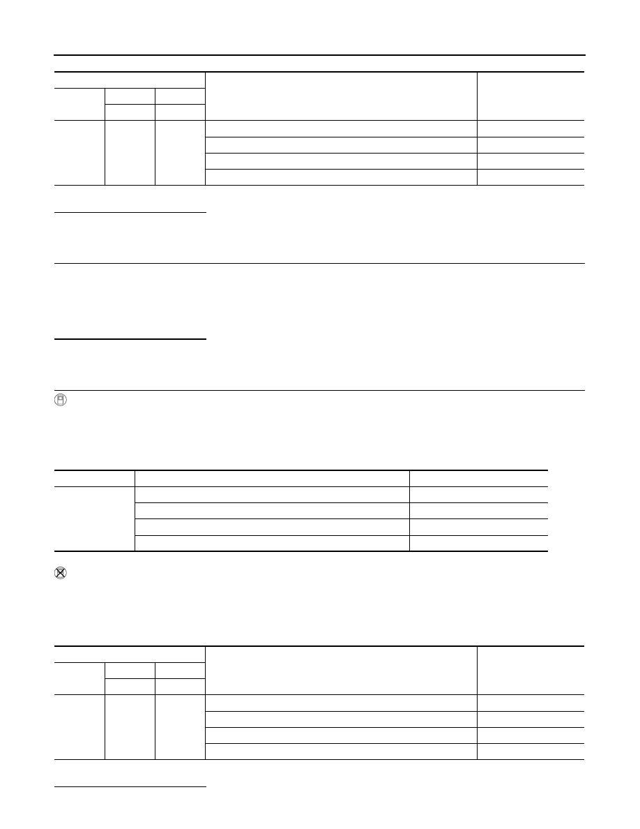
*: Check for linear voltage rise in response to engine being increased to approximately 4,000 rpm.
Is the inspection result normal?
YES
>> INSPECTION END
NO
>> GO TO 2.
2.
CHECK FOR THE CAUSE OF UNEVEN AIR FLOW THROUGH MASS AIR FLOW SENSOR
Check for the cause of uneven air flow through mass air flow sensor. Refer to the following.
• Crushed air ducts
• Malfunctioning seal of air cleaner element
• Uneven dirt of air cleaner element
• Improper specification of intake air system parts
Is the inspection result normal?
YES
>> GO TO 4.
NO
>> GO TO 3.
3.
CHECK MASS AIR FLOW SENSOR-II
With CONSULT
1.
Repair or replace malfunctioning part.
2.
Start engine and warm it up to normal operating temperature.
3.
Connect CONSULT and select “DATA MONITOR” mode.
4.
Select “MAS A/F SE-B1” and check indication under the following conditions.
*: Check for linear voltage rise in response to engine being increased to approximately 4,000 rpm.
Without CONSULT
1.
Repair or replace malfunctioning part.
2.
Start engine and warm it up to normal operating temperature.
3.
Check the voltage between ECM harness connector terminals under the following conditions.
*: Check for linear voltage rise in response to engine being increased to approximately 4,000 rpm.
Is the inspection result normal?
ECM
Condition
Voltage (V)
Connector
+
–
Terminal
Terminal
F8
58
(MAF sen-
sor signal)
56
(Sensor
ground)
Ignition switch ON (Engine stopped.)
Approx. 0.4
Idle (Engine is warmed-up to normal operating temperature.)
0.9 - 1.2
2,500 rpm (Engine is warmed-up to normal operating temperature.)
1.6 - 1.9
Idle to approximately 4,000 rpm
0.9 - 1.2 to Approx. 2.4*
Monitor item
Condition
MAS A/F SE-B1 (V)
MAS A/F SE-B1
Ignition switch ON (Engine stopped.)
Approx. 0.4
Idle (Engine is warmed-up to normal operating temperature.)
0.9 - 1.2
2,500 rpm (Engine is warmed-up to normal operating temperature.)
1.6 - 1.9
Idle to approximately 4,000 rpm
0.9 - 1.2 to Approx. 2.4*
ECM
Condition
Voltage (V)
Connector
+
–
Terminal
Terminal
F8
58
(MAF sen-
sor signal)
56
(Sensor
ground)
Ignition switch ON (Engine stopped.)
Approx. 0.4
Idle (Engine is warmed-up to normal operating temperature.)
0.9 - 1.2
2,500 rpm (Engine is warmed-up to normal operating temperature.)
1.6 - 1.9
Idle to approximately 4,000 rpm
0.9 - 1.2 to Approx. 2.4*