Nissan Murano. Manual - part 514


  Главная      Nissan     Nissan Murano (2014 year) - Service Manual


поиск по сайту            


содержание   ..  512  513  514  515   ..


Nissan Murano. Manual - part 514


EC-166

< DTC/CIRCUIT DIAGNOSIS >

[VQ35DE]

P0075, P0081 IVT CONTROL SOLENOID VALVE
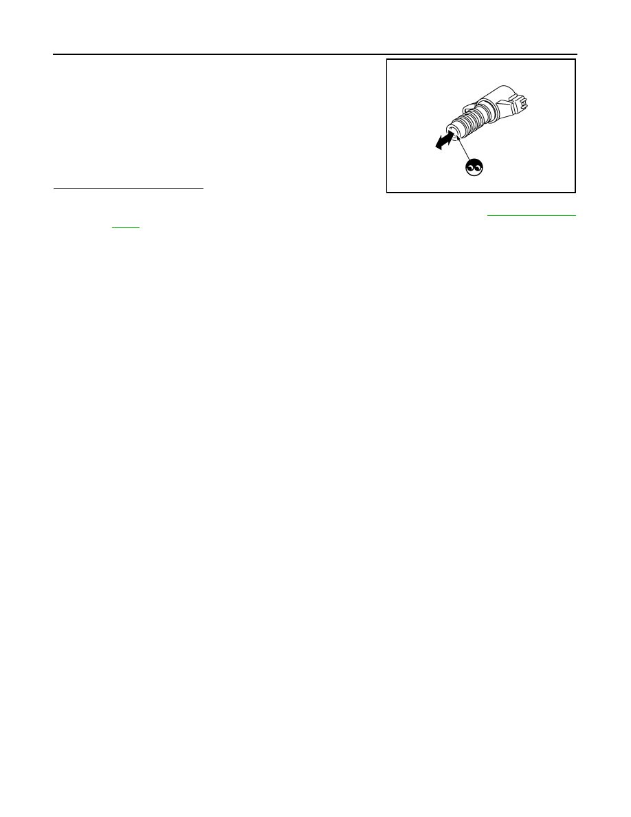
2.

Provide 12 V DC between intake valve timing control solenoid
valve terminals 1 and 2, and then interrupt it. Check that the
plunger moves as shown in the figure.

CAUTION:

Never apply 12 V DC continuously for 5 seconds or more.
Doing so may result in damage to the coil in intake valve
timing control solenoid valve.
NOTE:
Always replace O-ring when intake valve timing control
solenoid valve is removed.

Is the inspection result normal?

YES

>> INSPECTION END

NO

>> Replace malfunctioning intake valve timing control solenoid valve. Refer to 

EM-57, "Exploded

View"

.

JMBIA0079ZZ

P0101 MAF SENSOR

EC-167

< DTC/CIRCUIT DIAGNOSIS >

[VQ35DE]

C

D

E

F

G

H

I

J

K

L

M

A

EC

N

P

O

P0101 MAF SENSOR

Description

INFOID:0000000009719904

The mass air flow sensor (1) is placed in the stream of intake air. It
measures the intake flow rate by measuring a part of the entire
intake flow. The mass air flow sensor controls the temperature of the
hot wire to a certain amount. The heat generated by the hot wire is
reduced as the intake air flows around it. The greater air flow, the
greater the heat loss. 
Therefore, the electric current supplied to hot wire is changed to
maintain the temperature of the hot wire as air flow increases. The
ECM detects the air flow by means of this current change.

DTC Logic

INFOID:0000000009719905

DTC DETECTION LOGIC

NOTE:
If DTC P0101 is displayed with other DTC, first perform the trouble diagnosis for other DTC.

DTC CONFIRMATION PROCEDURE

1.

PRECONDITIONING

If DTC CONFIRMATION PROCEDURE has been previously conducted, always perform the following proce-
dure before conducting the next test.
1.

Turn ignition switch OFF and wait at least 10 seconds.

2.

Turn ignition switch ON.

3.

Turn ignition switch OFF and wait at least 10 seconds.

>> GO TO 2.

2.

PERFORM DTC CONFIRMATION PROCEDURE

1.

Start engine and warm it up to normal operating temperature.

2.

Drive the vehicle for at least 5 seconds under the following conditions:

CAUTION:

Always drive vehicle at safe speed.

NOTE:
• The gear must be fixed while driving the vehicle.
• Keep the accelerator pedal as steady as possible during cruising.

3.

Check 1st trip DTC.

Is 1st trip DTC detected?

YES

>> Proceed to 

EC-168, "Diagnosis Procedure"

.

NO

>> INSPECTION END

PBIA9559J

DTC No.

Trouble diagnosis

(Trouble diagnosis content)

DTC detecting condition

Possible cause

P0101

MAF SEN/CIRCUIT-B1
[Mass air flow (MAF) sensor cir-
cuit range/performance]

• A high voltage from the sensor is sent to 

ECM under light load driving condition.

• A low voltage from the sensor is sent to 

ECM under heavy load driving condition.

• Harness or connectors

(The sensor circuit is open or short-
ed.)

• Intake air leaks
• MAF sensor
• EVAP control system pressure sensor
• Intake air temperature sensor

Selector lever

Suitable position

Vehicle speed

40 km/h (25 MPH) or more

EC-168

< DTC/CIRCUIT DIAGNOSIS >

[VQ35DE]

P0101 MAF SENSOR

Diagnosis Procedure

INFOID:0000000009719906

1.

CHECK INTAKE SYSTEM

Check the following for connection.
• Air duct
• Vacuum hoses
• Intake air passage between air duct and intake manifold
Is the inspection result normal?

YES

>> GO TO 2.

NO

>> Reconnect the parts.

2.

CHECK GROUND CONNECTION

1.

Turn ignition switch OFF.

2.

Check ground connection E38. Refer to Ground Inspection in 

GI-47, "Circuit Inspection"

.

Is the inspection result normal?

YES

>> GO TO 3.

NO

>> Repair or replace ground connection.

3.

CHECK MASS AIR FLOW (MAF) SENSOR POWER SUPPLY CIRCUIT

1.

Disconnect MAF sensor harness connector.

2.

Turn ignition switch ON.

3.

Check the voltage between MAF sensor harness connector and ground.

Is the inspection result normal?

YES

>> GO TO 5.

NO

>> GO TO 4.

4.

DETECT MALFUNCTIONING PART

Check the following.
• Harness connectors E7, F121
• Harness for open or short between mass air flow sensor and IPDM E/R

>> Repair open circuit or short to ground or short to power in harness or connectors.

5.

CHECK MAF SENSOR GROUND CIRCUIT FOR OPEN AND SHORT

1.

Turn ignition switch OFF.

2.

Disconnect ECM harness connector.

3.

Check the continuity between MAF sensor harness connector and ECM harness connector.

4.

Also check harness for short to ground and short to power.

Is the inspection result normal?

YES

>> GO TO 6.

NO

>> Repair open circuit or short to ground or short to power in harness or connectors.

6.

CHECK MAF SENSOR INPUT SIGNAL CIRCUIT FOR OPEN AND SHORT

1.

Check the continuity between MAF sensor harness connector and ECM harness connector.

MAF sensor

Ground

Voltage

Connector

Terminal

F4

5

Ground

Battery voltage

MAF sensor

ECM

Continuity

Connector

Terminal

Connector

Terminal

F4

4

F8

56

Existed

P0101 MAF SENSOR

EC-169

< DTC/CIRCUIT DIAGNOSIS >

[VQ35DE]

C

D

E

F

G

H

I

J

K

L

M

A

EC

N

P

O

2.

Also check harness for short to ground and short to power.

Is the inspection result normal?

YES

>> GO TO 7.

NO

>> Repair open circuit or short to ground or short to power in harness or connectors.

7.

CHECK INTAKE AIR TEMPERATURE SENSOR

Check intake air temperature sensor. Refer to 

EC-180, "Component Inspection"

.

Is the inspection result normal?

YES

>> GO TO 8.

NO

>> Replace MAF sensor (with intake air temperature sensor).

8.

CHECK EVAP CONTROL SYSTEM PRESSURE SENSOR

Check EVAP control system pressure sensor. Refer to 

EC-312, "Component Inspection"

.

Is the inspection result normal?

YES

>> GO TO 9.

NO

>> Replace EVAP control system pressure sensor.

9.

CHECK MAF SENSOR

Check MAF sensor. Refer to 

EC-169, "Component Inspection"

.

Is the inspection result normal?

YES

>> GO TO 10.

NO

>> Replace MAF sensor. Refer to 

EM-31, "Exploded View"

.

10.

CHECK INTERMITTENT INCIDENT

Check intermittent incident. Refer to 

GI-44, "Intermittent Incident"

.

>> INSPECTION END

Component Inspection

INFOID:0000000009719907

1.

CHECK MASS AIR FLOW SENSOR-I

With CONSULT

1.

Reconnect all harness connectors disconnected.

2.

Start engine and warm it up to normal operating temperature.

3.

Connect CONSULT and select “DATA MONITOR” mode.

4.

Select “MAS A/F SE-B1” and check indication under the following conditions.

*: Check for linear voltage rise in response to engine being increased to approximately 4,000 rpm.

Without CONSULT

1.

Reconnect all harness connectors disconnected.

2.

Start engine and warm it up to normal operating temperature.

3.

Check the voltage between ECM harness connector terminals under the following conditions.

MAF sensor

ECM

Continuity

Connector

Terminal

Connector

Terminal

F4

3

F8

58

Existed

Monitor item

Condition

MAS A/F SE-B1 (V)

MAS A/F SE-B1

Ignition switch ON (Engine stopped.)

Approx. 0.4

Idle (Engine is warmed-up to normal operating temperature.)

0.9 - 1.2

2,500 rpm (Engine is warmed-up to normal operating temperature.)

1.6 - 1.9

Idle to approximately 4,000 rpm

0.9 - 1.2 to Approx. 2.4*


содержание   ..  512  513  514  515   ..