Nissan Murano. Manual - part 460


  Главная      Nissan     Nissan Murano (2014 year) - Service Manual


поиск по сайту            


содержание   ..  458  459  460  461   ..


Nissan Murano. Manual - part 460


TRANSFER CASE

DLN-79

< UNIT DISASSEMBLY AND ASSEMBLY >

[TRANSFER: TY20A]

C

E

F

G

H

I

J

K

L

M

A

B

DLN

N

O

P

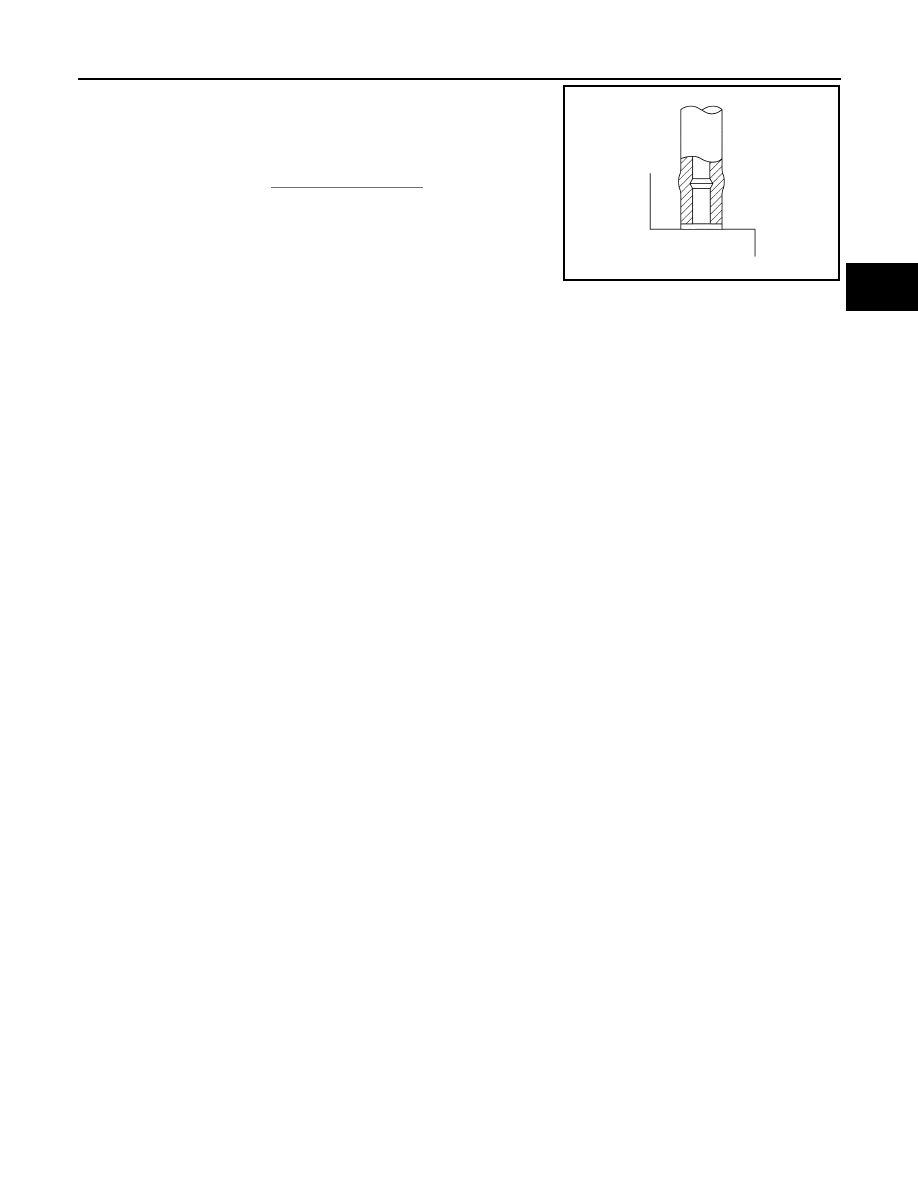
• Be sure to insert air breather hose into breather tube

(metal connector) until hose end reaches the tube’s base.

• Be sure to insert air breather hose in the hole of the trans-

fer case.

11. Check backlash, tooth contact, total preload and companion

flange runout. Refer to 

DLN-69, "Adjustment"

.

CAUTION:

Measure the total preload without the adapter case oil
seals.

Inspection

INFOID:0000000009718160

Check items below. If necessary, replace them with new ones.

CASE

Check the bearing mounting surface for wear, cracks and damages.

SCIA2663J

DLN-80

< SERVICE DATA AND SPECIFICATIONS (SDS) 

[TRANSFER: TY20A]

SERVICE DATA AND SPECIFICATIONS (SDS)

SERVICE DATA AND SPECIFICATIONS (SDS)

SERVICE DATA AND SPECIFICATIONS (SDS)

General Specifications

INFOID:0000000009718161

Preload Torque

INFOID:0000000009718162

BEFORE DISASSEMBLY

Unit: N·m (kg-m, in-lb)

AFTER DISASSEMBLY AND REASSEMBLY

Unit: N·m (kg-m, in-lb)

Backlash

INFOID:0000000009718163

Unit: mm (in)

Companion Flange Runout

INFOID:0000000009718164

Unit: mm (in)

Applied model

AWD

VQ35DE

CVT

Transfer model

TY20A

Oil capacity (Approx.)

 (US pt, lmp pt)

0.31 (5/8, 1/2)

Gear ratio

0.404

Number of teeth

Ring gear

42

Drive pinion

17

Item

Standard

Drive pinion bearing preload (P

1

)

0.10 – 0.39 (0.01 – 0.03, 1.0 – 3.0)

Total preload

With all oil seals

P

1

 + 0.16 – 0.22 (0.017 – 0.022, 1.5 – 1.9)

Without transfer oil seal and 
adapter case oil seal

P

1

 + 0.06 – 0.12 (0.007 – 0.012, 0.6 – 1.0)

Item

Standard

Drive pinion bearing preload (P

1

)

0.50 – 0.99 (0.06 – 0.10, 5 – 8)

Total preload

With all oil seals

P

1

 + 0.49 – 0.63 (0.05 – 0.06, 4.4 – 5.5)

Without transfer oil seal and 
adapter case oil seal

P

1

 + 0.27 – 0.41 (0.03 – 0.04, 2.4 – 3.6)

Item

Standard

Ring gear to drive pinion

0.17 – 0.24 (0.0067 – 0.0094)

Item

Limit

Companion flange face (inner side of the propeller shaft bolt holes)

0.15 (0.0059)

Inside of companion flange (socket diameter)

0.2 (0.008)

NOISE, VIBRATION AND HARSHNESS (NVH) TROUBLESHOOTING

DLN-81

< SYMPTOM DIAGNOSIS >

[REAR PROPELLER SHAFT: 3F63A-EDJ75]

C

E

F

G

H

I

J

K

L

M

A

B

DLN

N

O

P

SYMPTOM DIAGNOSIS

NOISE, VIBRATION AND HARSHNESS (NVH) TROUBLESHOOTING

NVH Troubleshooting Chart

INFOID:0000000009718165

Use the chart below to find the cause of the symptom. If necessary, repair or replace these parts.

×

: Applicable

Reference

DLN-84, "

Inspe

c

tio

n

"

DLN-87, "

Inspe

c

tio

n

"

DLN-87, "

Inspe

c

tio

n

"

DLN-87, "

Inspe

c

tio

n

"

DLN-84, "

Inspe

c

tio

n

"

NVH of REAR FINAL 

DR

IVE in this section

NVH in F

AX, RAX

, FSU 

and RSU section

NVH in WT

 se

ct

io

n

NVH in WT

 se

ct

io

n

NVH in F

AX and RAX section

NVH in BR section

NVH in ST 

section

Possible cause and SUSPECTED PARTS

Un

ev

en

 rot

a

ti

ng

 to

rq

ue

Ce

nt

e

r be

ari

n

g

 im

pro

p

e

in

st

al

la

ti

on

Exc

e

s

s

ive

 c

e

n

ter 

be

arin

ax

ia

l e

n

d

 pl

ay

Ce

nt

e

r be

ari

n

g

 mou

n

ti

n

g

 (in

su

lat

or) c

rack

s,

 da

ma

ge

 or de

te

ri

ora

tio

n

Ex

ce

ssi

v

e

 jo

in

t an

gl

e

Ro

tat

ion

 i

m

ba

la

nc

e

Ex

ce

ssi

v

e

 run

o

u

t

DIFFERENTIAL

AXLE

 AND SUSPE

N

S

ION

TIRE

ROA

D

 WHEEL

DR

IVE SHAF

T

BRAKE

STEERING

Symptom

Noise

×

×

×

×

×

×

×

×

×

×

×

×

×

×

Shake

×

×

×

×

×

×

×

×

Vibration

×

×

×

×

×

×

×

×

×

×

×

DLN-82

< PRECAUTION >

[REAR PROPELLER SHAFT: 3F63A-EDJ75]

PRECAUTIONS

PRECAUTION

PRECAUTIONS

Precautions for Removing of Battery Terminal

INFOID:0000000010084831

•  When removing the 12V battery terminal, turn OFF the ignition

switch and wait at least 30 seconds.
NOTE:
ECU may be active for several tens of seconds after the ignition
switch is turned OFF. If the battery terminal is removed before ECU
stops, then a DTC detection error or ECU data corruption may
occur.

•  For vehicles with the 2-batteries, be sure to connect the main bat-

tery and the sub battery before turning ON the ignition switch.
NOTE:
If the ignition switch is turned ON with any one of the terminals of
main battery and sub battery disconnected, then DTC may be
detected.

•  After installing the 12V battery, always check "Self Diagnosis Result" of all ECUs and erase DTC.

NOTE:
The removal of 12V battery may cause a DTC detection error.

SEF289H


содержание   ..  458  459  460  461   ..