Nissan Murano. Manual - part 439


  Главная      Nissan     Nissan Murano (2014 year) - Service Manual


поиск по сайту            


содержание   ..  437  438  439  440   ..


Nissan Murano. Manual - part 439


INTELLIGENT KEY BATTERY

DLK-367

< REMOVAL AND INSTALLATION >

[WITH INTELLIGENT KEY SYSTEM]

C

D

E

F

G

H

I

J

L

M

A

B

DLK

N

O

P

INTELLIGENT KEY BATTERY

Removal and Installation

INFOID:0000000009719297

1.

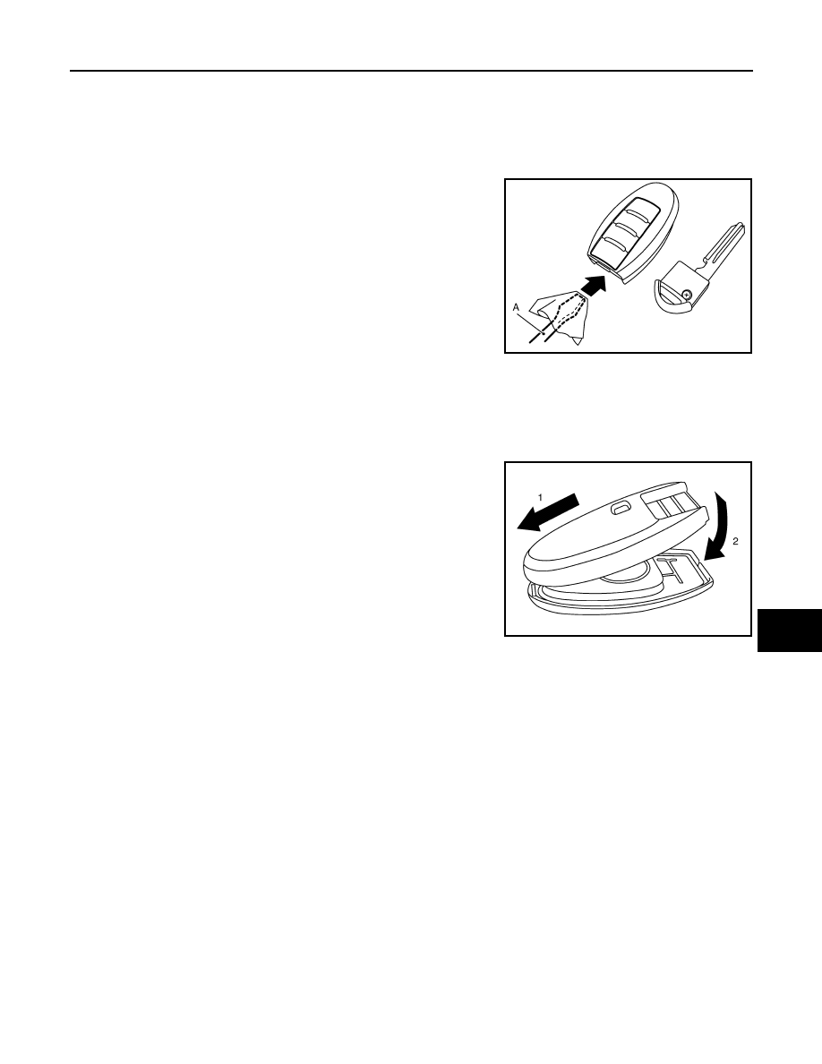
Release the lock knob at the back of the Intelligent Key and remove the mechanical key.

2.

Insert a remover tool (A) wrapped with a cloth into the slit of the
corner and twist it to separate the upper part from the lower part.

CAUTION:

• Do not touch the circuit board or battery terminal.
• The key fob is water-resistant. However, if it does get wet,

immediately wipe it dry. 

3.

Replace the battery with new one.

4.

Align the tips of the upper and lower parts, and then push them
together until it is securely closed.

CAUTION:

• When replacing battery, keep dirt, grease, and other for-

eign materials off the electrode contact area.

• After replacing the battery, check that all Intelligent Key

functions work normally.

PIIB6221E

Battery replacement

:Coin-type lithium battery 
(CR2025)

PIIB6222E

DLK-368

< REMOVAL AND INSTALLATION >

[WITH INTELLIGENT KEY SYSTEM]

AUTOMATIC BACK DOOR CONTROL UNIT

AUTOMATIC BACK DOOR CONTROL UNIT

Exploded View

INFOID:0000000009719298

Removal and Installation

INFOID:0000000009719299

REMOVAL

1.

Remove the luggage side finisher lower (RH). Refer to 

INT-35, "Removal and Installation"

.

2.

Remove the automatic back door control unit bracket mounting
bolt (A) and nats (B), and then remove the automatic back door
control unit bracket.

3.

Remove the automatic back door control unit mounting bolt, and then remove the automatic back door
control unit.

INSTALLATION

Install in the reverse order of removal.
NOTE:
After installing back door control unit, perform additional service when replace control unit. Refer to 

DLK-13,

"ADDITIONAL SERVICE WHEN REPLACING CONTROL UNIT : Special Repair Requirement"

.

1.

Automatic back door control unit

2.

Automatic back door control unit bracket

JMKIA2125ZZ

JMKIA2124ZZ

AUTOMATIC BACK DOOR WARNING BUZZER

DLK-369

< REMOVAL AND INSTALLATION >

[WITH INTELLIGENT KEY SYSTEM]

C

D

E

F

G

H

I

J

L

M

A

B

DLK

N

O

P

AUTOMATIC BACK DOOR WARNING BUZZER

Exploded View

INFOID:0000000009719300

Refer to 

EXT-18, "Exploded View"

.

Removal and Installation

INFOID:0000000009719301

REMOVAL

1.

Remove the rear bumper. Refer to 

EXT-18, "Removal and Installation"

.

2.

Remove the automatic back door warning buzzer mounting nut
(A), and then remove the automatic back door warning buzzer
(1).

INSTALLATION

Install in the reverse order of removal.

JMKIA2123ZZ

DLK-370

< REMOVAL AND INSTALLATION >

[WITH INTELLIGENT KEY SYSTEM]

AUTOMATIC BACK DOOR MAIN SWITCH

AUTOMATIC BACK DOOR MAIN SWITCH

Exploded View

INFOID:0000000009719302

Refer to 

IP-14, "Exploded View"

.

Removal and Installation

INFOID:0000000009719303

REMOVAL

1.

Remove the instrument driver lower panel LH. Refer to 

IP-15, "Removal and Installation"

.

2.

Widen the pawl, and remove the automatic back door main switch (1) from switch bracket (2).

INSTALLATION

Install in the reverse order of removal.

:

Pawl

JMKIA1849ZZ


содержание   ..  437  438  439  440   ..