Nissan Murano. Manual - part 435


  Главная      Nissan     Nissan Murano (2014 year) - Service Manual


поиск по сайту            


содержание   ..  433  434  435  436   ..


Nissan Murano. Manual - part 435


BACK DOOR LOCK

DLK-351

< REMOVAL AND INSTALLATION >

[WITH INTELLIGENT KEY SYSTEM]

C

D

E

F

G

H

I

J

L

M

A

B

DLK

N

O

P

BACK DOOR LOCK

DOOR LOCK

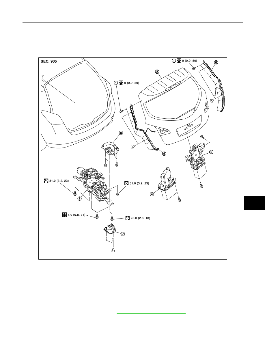
DOOR LOCK : Exploded View

INFOID:0000000009719269

DOOR LOCK : Removal and Installation

INFOID:0000000009719270

REMOVAL

1.

Remove back door finisher inner. Refer to 

INT-38, "Removal and Installation"

.

2.

Disconnect back door lock assembly and back door opener switch connectors.

3.

Remove back door lock mounting bolts, and then remove back door lock assembly.

JMKIA1804GB

1.

TORX bolt

2.

Back door assembly

3.

Power back door drive assembly

4.

Back door lock assembly (normal)

5.

Back door lock assembly (super lock)

6.

Touch sensor (RH/LH)

7.

Cover

8.

Patch

Refer to 

GI-4, "Components"

 for symbols in the figure.

DLK-352

< REMOVAL AND INSTALLATION >

[WITH INTELLIGENT KEY SYSTEM]

BACK DOOR LOCK

INSTALLATION

Install in the reverse order of removal.

CAUTION:

Check back door open/close, lock/unlock operation after installation. 

POWER BACK DOOR DRIVE ASSEMBLY

POWER BACK DOOR DRIVE ASSEMBLY : Exploded View

INFOID:0000000009719271

POWER BACK DOOR DRIVE ASSEMBLY : Removal and Installation

INFOID:0000000009719272

REMOVAL

JMKIA1804GB

1.

TORX bolt

2.

Back door assembly

3.

Power back door drive assembly

4.

Back door lock assembly (normal)

5.

Back door lock assembly (super lock)

6.

Touch sensor (RH/LH)

7.

Cover

8.

Patch

Refer to 

GI-4, "Components"

 for symbols in the figure.

BACK DOOR LOCK

DLK-353

< REMOVAL AND INSTALLATION >

[WITH INTELLIGENT KEY SYSTEM]

C

D

E

F

G

H

I

J

L

M

A

B

DLK

N

O

P

1.

Remove headlining. Refer to 

INT-26, "NORMAL ROOF : Removal and Installation"

 (NORMAL ROOF),

INT-30, "SUNROOF : Removal and Installation"

 (SUNROOF).

2.

Disconnect power back door drive assembly connector.

3.

Remove mounting bolts of power back door drive assembly (1)
(back door side).

4.

Remove mounting bolts of power back door drive assembly (1)
(body side), and then remove power back door drive assembly.

CAUTION:

Remove the bolts of power back door drive assembly refer-
ring to figure. 

INSTALLATION

Install in the reverse order of removal.

CAUTION:

• Install the bolts of power back door drive assembly in the reverse order of removal.
• Check back door open/close operation after installation. 

TOUCH SENSOR

JMKIA1918ZZ

JMKIA1919ZZ

DLK-354

< REMOVAL AND INSTALLATION >

[WITH INTELLIGENT KEY SYSTEM]

BACK DOOR LOCK

TOUCH SENSOR : Exploded View

INFOID:0000000009719273

TOUCH SENSOR : Removal and Installation

INFOID:0000000009719274

CAUTION:

Take care not to bend touch sensor.

REMOVAL

1.

Remove back door finisher inner. Refer to 

INT-38, "Removal and Installation"

.

2.

Disconnect touch sensor connector.

JMKIA1804GB

1.

TORX bolt

2.

Back door assembly

3.

Power back door drive assembly

4.

Back door lock assembly (normal)

5.

Back door lock assembly (super lock)

6.

Touch sensor (RH/LH)

7.

Cover

8.

Patch

Refer to 

GI-4, "Components"

 for symbols in the figure.


содержание   ..  433  434  435  436   ..