Nissan Murano. Manual - part 431


  Главная      Nissan     Nissan Murano (2014 year) - Service Manual


поиск по сайту            


содержание   ..  429  430  431  432   ..


Nissan Murano. Manual - part 431


BACK DOOR

DLK-335

< REMOVAL AND INSTALLATION >

[WITH INTELLIGENT KEY SYSTEM]

C

D

E

F

G

H

I

J

L

M

A

B

DLK

N

O

P

INSTALLATION

Install in the reverse order of removal.

CAUTION:

Check back door open/close operation after installation.

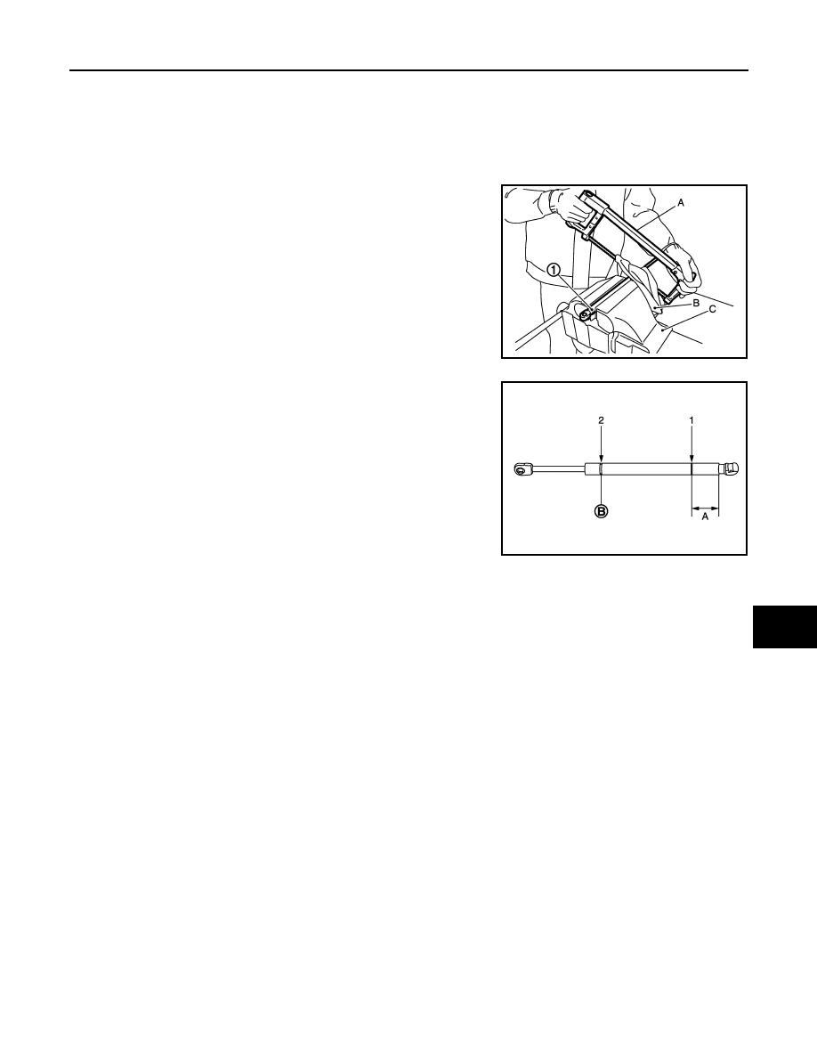
BACK DOOR STAY : Disposal 

INFOID:0000000009719251

1.

Fix back door stay (1) using a vise (C).

2.

Using hacksaw (A) slowly make 2 holes in the back door stay, in
numerical order as shown in the figure.

CAUTION:

• When cutting a hole on back door stay, always cover a

hacksaw using a shop cloth (B) to avoid scattering metal
fragments or oil. 

• Wear eye protection (safety glasses).
• Wear gloves.

BACK DOOR WEATHER-STRIP

JMKIA3336ZZ

A:

20 mm (0.787 in)

B:

Cut at the groove.

JMKIA3609ZZ

DLK-336

< REMOVAL AND INSTALLATION >

[WITH INTELLIGENT KEY SYSTEM]

BACK DOOR

BACK DOOR WEATHER-STRIP : Exploded View

INFOID:0000000009719252

BACK DOOR WEATHER-STRIP : Removal and Installation

INFOID:0000000009719253

REMOVAL

1.

Remove mounting bolts of power back door drive assembly (1)
(back door side).

2.

Pull up and remove engagement with body from weather-strip joint.

CAUTION:

Never pull strongly on weather-strip.

INSTALLATION

1.

Working from the upper section, align weather-strip center mark (A) with vehicle center mark (cutting posi-
tion) and install weather-strip onto the vehicle.

1.

Back door stay

2.

Back door hinge

3.

Back door striker

4.

Bumper rubber

5.

Back door weather-strip

6.

Back door assembly

7.

Stud ball

A

: Center mark

B

: Front mark

: Vehicle front

Refer to 

GI-4, "Components"

 for symbols in the figure.

JMKIA3496ZZ

JMKIA1918ZZ

BACK DOOR

DLK-337

< REMOVAL AND INSTALLATION >

[WITH INTELLIGENT KEY SYSTEM]

C

D

E

F

G

H

I

J

L

M

A

B

DLK

N

O

P

2.

For the lower section, align weather-strip seam with center of back door striker.

3.

Pull weather-strip gently to ensure that there is no loose section.
NOTE:
Make sure that weather-strip is fit tightly at each corner and luggage rear plate.

4.

Install mounting bolts of power back door drive assembly (back door side).

DLK-338

< REMOVAL AND INSTALLATION >

[WITH INTELLIGENT KEY SYSTEM]

HOOD LOCK

HOOD LOCK

Exploded View

INFOID:0000000009719254

Removal and Installation

INFOID:0000000009719255

REMOVAL

CAUTION:

Check wiring of hood lock control before removal.
1.

Remove front grille. Refer to 

EXT-21, "Removal and Installation"

.

2.

Remove mounting bolts, and then remove hood lock assembly
(1). 
NOTE:
Press the lever downward to avoid pin (A), then pull out hood
lock assembly upward.

3.

Disconnect hood lock cable (2) from hood lock assembly.

4.

Remove instrument lower panel (LH). Refer to 

IP-15, "Removal and Installation"

.

5.

Disconnect hood lock cable from instrument lower panel (LH).

6.

Remove fender protector (LH). Refer to 

EXT-26, "FENDER PROTECTOR : Removal and Installation"

.

7.

Remove hood lock cable clamp.

1.

Hood lock assembly

2.

Hood lock control cable

3.

Hood lock opener

: Clip

Refer to 

GI-4, "Components"

 for symbols in the figure.

JMKIA1798ZZ

JMKIA1914ZZ


содержание   ..  429  430  431  432   ..