содержание .. 297 298 299 300 ..
Nissan Murano. Manual - part 299
DAS-86
< DTC/CIRCUIT DIAGNOSIS >
[LDW]
WASHER LEVEL SWITCH SIGNAL CIRCUIT
WASHER LEVEL SWITCH SIGNAL CIRCUIT
Diagnosis Procedure
INFOID:0000000009723283
1.
CHECK WASHER LEVEL SWITCH INPUT SIGNAL CIRCUIT
1.
Turn ignition switch OFF.
2.
Disconnect combination meter connector and camera control unit.
3.
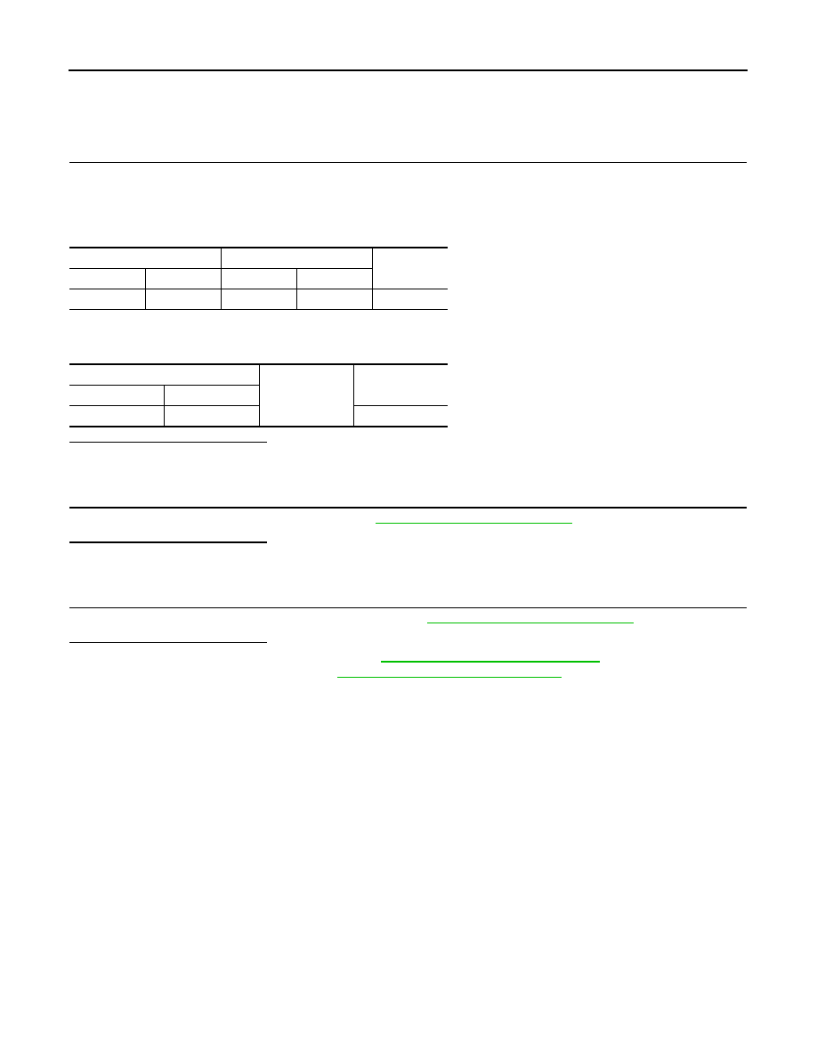
Check continuity between combination meter harness connector and camera control unit harness connec-
tor.
4.
Disconnect washer level switch harness connector.
5.
Check continuity between camera control unit harness connector and the ground.
Is the inspection result normal?
YES
>> GO TO 2.
NO
>> Repair harness or connector.
2.
CHECK WASHER LEVEL SWITCH SIGNAL CIRCUIT
Check washer level switch signal circuit. Refer to
Is the inspection result normal?
YES
>> GO TO 3.
NO
>> Repair harness or connector.
3.
CHECK WASHER LEVEL SWITCH
Perform a unit check for the washer level switch. Refer to
MWI-50, "Component Inspection"
Is the inspection result normal?
YES
>> Replace camera control unit. Refer to
DAS-94, "Removal and Installation"
.
NO
>> Replace washer tank. Refer to
WW-128, "Removal and Installation"
Combination meter
Camera control unit
Continuity
Connector
Terminal
Connector
Terminal
M34
29
B93
40
Existed
Camera control unit
Ground
Continuity
Connector
Terminal
B93
40
Not existed