Nissan Murano. Manual - part 297


  Главная      Nissan     Nissan Murano (2014 year) - Service Manual


поиск по сайту            


содержание   ..  295  296  297  298   ..


Nissan Murano. Manual - part 297


DAS-78

< DTC/CIRCUIT DIAGNOSIS >

[LDW]

WARNING SYSTEMS ON INDICATOR CIRCUIT

WARNING SYSTEMS ON INDICATOR CIRCUIT

Component Function Check

INFOID:0000000009723274

1.

CHECK WARNING SYSTEMS ON INDICATOR

1.

Turn the ignition switch ON.

2.

Select the ACTIVE TEST item “ITS SW 1 IND” of “AVM” with CONSULT.

3.

With operating the test item, check the operation.

Is the inspection result normal?

YES

>> Warning systems switch indicator circuit is normal.

NO

>> Refer to 

DAS-78, "Diagnosis Procedure"

.

Diagnosis Procedure

INFOID:0000000009723275

1.

CHECK WARNING ON INDICATOR POWER SUPPLY CIRCUIT

1.

Turn ignition switch OFF.

2.

Disconnect warning systems switch connector.

3.

Check voltage between warning systems switch harness connector and ground.

Is the inspection result normal?

YES

>> GO TO 2.

NO

>> Repair the warning systems ON indicator power supply circuit.

2.

CHECK WARNING SYSTEMS ON INDICATOR SIGNAL FOR OPEN

1.

Disconnect the camera control unit harness connector.

2.

Check continuity between the camera control unit harness connector and warning systems switch har-
ness connector.

Is the inspection result normal?

YES

>> GO TO 3.

NO

>> Repair the harnesses or connectors.

3.

CHECK WARNING SYSTEMS ON INDICATOR SIGNAL CIRCUIT FOR SHORT

Check continuity between the camera control unit harness connector and ground.

Is the inspection result normal?

YES

>> GO TO 4.

NO

>> Repair the harnesses or connectors.

On

: Warning systems ON indicator illuminates

Off

: Warning systems ON indicator is turned OFF
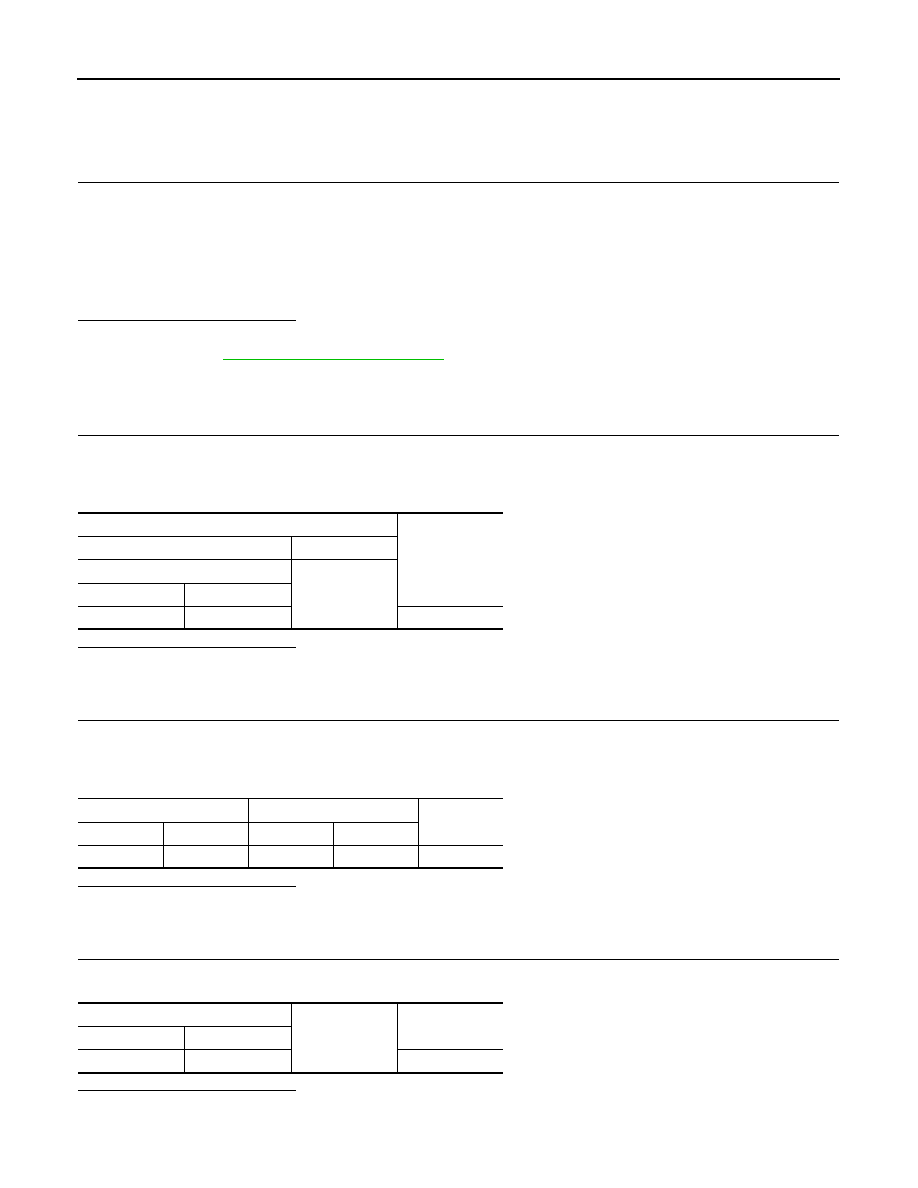
Terminals

Voltage

(Approx.)

(+)

(

)

Warning systems switch

Ground

Connector

Terminal

M39

3

Battery voltage

Camera control unit

Warning systems switch

Continuity

Connector

Terminal

Connector

Terminal

B92

15

M39

2

Existed

Camera control unit

Ground

Continuity

Connector

Terminal

B92

15

Not existed

DAS

WARNING SYSTEMS ON INDICATOR CIRCUIT

DAS-79

< DTC/CIRCUIT DIAGNOSIS >

[LDW]

C

D

E

F

G

H

I

J

K

L

M

B

N

P

A

4.

CHECK WARNING SYSTEMS ON INDICATOR

Check the warning systems ON indicator. Refer to 

DAS-79, "Component Inspection"

.

Is the inspection result normal?

YES

>> Replace the camera control unit. Refer to 

DAS-94, "Removal and Installation"

.

NO

>> Replace warning systems switch. 

DAS-101, "Removal and Installation"

.

Component Inspection

INFOID:0000000009723276

1.

CHECK WARNING SYSTEMS ON INDICATOR

Apply battery voltage to warning systems switch terminals 1 and 2, and then check if the warning systems ON
indicator illuminates.

Is the inspection result normal?

YES

>> INSPECTION END

NO

>> Replace the warning systems switch. Refer to 

DAS-101, "Removal and Installation"

.

Terminals

Condition

Warning sys-

tems ON indica-

tor

(+)

(-)

3

2

When the battery voltage is applied

On

When the battery voltage is not applied

Off

DAS-80

< DTC/CIRCUIT DIAGNOSIS >

[LDW]

REAR VIEW CAMERA WASHER RELAY CIRCUIT

REAR VIEW CAMERA WASHER RELAY CIRCUIT

Component Function Check

INFOID:0000000009723277

1.

CHECK REAR VIEW CAMERA WASHER RELAY CIRCUIT

1.

Turn the ignition switch ON.

2.

Select the ACTIVE TEST item “WASH ACTIVE” of “AVM” with CONSULT.

3.

With operating the test item, check the operation.

Is the inspection result normal?

YES

>> Washer rear view camera washer relay circuit is normal.

NO

>> Refer to 

DAS-83, "Diagnosis Procedure"

.

Diagnosis Procedure

INFOID:0000000009723278

1.

CHECK REAR VIEW CAMERA WASHER RELAY 1 POWER SUPPLY CIRCUIT

1.

Turn the ignition switch ON.

2.

Check voltage between rear view camera washer relay 1 harness connector and ground.

Is the inspection result normal?

YES

>> GO TO 2.

NO

>> Repair rear view camera washer relay 1 power supply circuit.

2.

CHECK REAR VIEW CAMERA WASHER RELAY 1 GROUND CIRCUIT

1.

Turn ignition switch OFF.

2.

Disconnect rear view camera washer relay 1.

3.

Disconnect pump control unit connector.

4.

Check continuity between rear view camera washer relay 1 harness connector and the pump control unit
harness connector.

5.

Check continuity between rear view camera washer relay 1 harness connector and the ground.

Is the inspection result normal?

YES

>> GO TO 3.

NO

>> Repair harness or connector.

3.

CHECK REAR VIEW CAMERA WASHER RELAY 2 POWER SUPPLY CIRCUIT

1.

Turn the ignition switch ON.

2.

Check voltage between rear view camera washer relay 2 harness connector and ground.

On

: Rear view camera washer is activated.

Off

: Rear view camera washer is not activated.

Terminals

Voltage

(Approx.)

(+)

(

)

Rear view camera washer relay 1

Ground

Connector

Terminal

E29

1

Battery voltage

Rear view camera washer 

relay 1

Pump control unit

Continuity

Connector

Terminal

Connector

Terminal

E29

2

D170

4

Existed

Rear view camera washer relay 1

Ground

Continuity

Connector

Terminal

E29

2

Not existed

DAS

REAR VIEW CAMERA WASHER RELAY CIRCUIT

DAS-81

< DTC/CIRCUIT DIAGNOSIS >

[LDW]

C

D

E

F

G

H

I

J

K

L

M

B

N

P

A

Is the inspection result normal?

YES

>> GO TO 4.

NO

>> Repair rear view camera washer relay 2 power supply circuit.

4.

CHECK REAR VIEW CAMERA WASHER RELAY 2 GROUND CIRCUIT

1.

Turn ignition switch OFF.

2.

Disconnect rear view camera washer relay 2.

3.

Check continuity between rear view camera washer relay 2 harness connector and the pump control unit
harness connector.

4.

Check continuity between rear view camera washer relay 2 harness connector and the ground.

Is the inspection result normal?

YES

>> GO TO 5.

NO

>> Repair harness or connector.

5.

CHECK REAR VIEW CAMERA WASHER RELAY 1 AND 2

Check rear view camera washer relay 1 and 2. Refer to 

DAS-81, "Component Inspection"

.

Is the inspection result normal?

YES

>> Replace pump control unit.

NO

>> Repair harness or connector.

Component Inspection

INFOID:0000000009723279

1.

CHECK REAR VIEW CAMERA WASHER RELAY 1

Apply battery voltage to rear view camera washer relay terminals 1 and 2, and then check for continuity under
the following conditions.

Is the inspection result normal?

YES

>> GO TO 2.

NO

>> Replace rear view camera washer relay 1.

2.

CHECK REAR VIEW CAMERA WASHER RELAY 2

Terminals

Voltage

(Approx.)

(+)

(

)

Rear view camera washer relay 2

Ground

Connector

Terminal

E28

1

Battery voltage

Rear view camera washer 

relay 2

Pump control unit

Continuity

Connector

Terminal

Connector

Terminal

E28

2

D170

3

Existed

Rear view camera washer relay 2

Ground

Continuity

Connector

Terminal

E28

2

Not existed

Terminal

Condition

Continuity

5

3

When the battery voltage is applied

Existed

When the battery voltage is not applied

Not existed

4

3

When the battery voltage is applied

Not existed

When the battery voltage is not applied

Existed


содержание   ..  295  296  297  298   ..