содержание .. 294 295 296 297 ..
Nissan Murano. Manual - part 296
DAS-74
< DTC/CIRCUIT DIAGNOSIS >
[LDW]
POWER SUPPLY AND GROUND CIRCUIT
POWER SUPPLY AND GROUND CIRCUIT
CAMERA CONTROL UNIT
CAMERA CONTROL UNIT : Diagnosis Procedure
INFOID:0000000009723269
1.
CHECK FUSE
Check for blown fuses.
Is the inspection result normal?
YES
>> GO TO 2.
NO
>> Be sure to eliminate cause of malfunction before installing new fuse.
2.
CHECK CAMERA CONTROL UNIT POWER SUPPLY CIRCUIT
Check voltage between camera control unit harness connector and ground.
Is the inspection result normal?
YES
>> GO TO 3.
NO
>> Repair the camera control unit power supply circuit.
3.
CHECK CAMERA CONTROL UNIT GROUND CIRCUIT
1.
Turn the ignition switch OFF.
2.
Disconnect the camera control unit connector.
3.
Check for continuity between camera control unit harness connector and ground.
Is the inspection result normal?
YES
>> INSPECTION END
NO
>> Repair the camera control unit ground circuit.
PUMP CONTROL UNIT
PUMP CONTROL UNIT : Diagnosis Procedure
INFOID:0000000009723270
1.
CHECK FUSE
Check for blown fuses.
Is the inspection result normal?
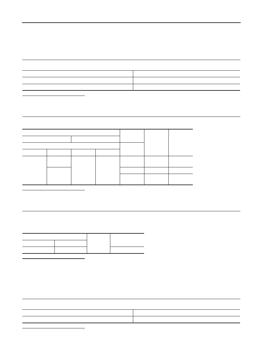
Power source
Fuse No.
Battery power supply
6
Ignition signal
3
Terminal
Condition
Standard
voltage
Reference
voltage
(Approx.)
(+)
(–)
Camera control unit
Ignition
switch
Connector
Terminal
Connector
Terminal
B92
2
B92
1
OFF
9.5 - 16 V
Battery volt-
age
3
OFF
0 - 0.1 V
0 V
ON
9.5 - 16 V
Battery volt-
age
Camera control unit
Ground
Continuity
Connector
Terminal
B92
1
Existed
Power source
Fuse No.
Ignition power supply
47