содержание .. 291 292 293 294 ..
Nissan Murano. Manual - part 293
DAS-62
< DTC/CIRCUIT DIAGNOSIS >
[LDW]
U0416 ABS ACTUATOR AND ELECTRIC UNIT (CONTROL UNIT)
U0416 ABS ACTUATOR AND ELECTRIC UNIT (CONTROL UNIT)
DTC Logic
INFOID:0000000009723245
DTC DETECTION LOGIC
NOTE:
If DTC “U0416” is detected along with DTC “U1000”, first diagnose the DTC “U1000”. Refer to
.
DTC CONFIRMATION PROCEDURE
1.
PERFORM DTC CONFIRMATION PROCEDURE
1.
Start the engine.
2.
Turn the LDW system ON.
3.
Perform “All DTC Reading” with CONSULT.
4.
Check if the “U0416” is detected as the current malfunction in “Self Diagnostic Result” of “AVM”.
Is “U0416” detected as the current malfunction?
YES
>> Refer to
.
NO
>> Refer to
GI-44, "Intermittent Incident"
.
Diagnosis Procedure
INFOID:0000000009723246
1.
CHECK SELF-DIAGNOSIS RESULTS
Check if “U1000” is detected other than “U0416” in “Self Diagnostic Result” of “AVM”.
Is “U1000” detected?
YES
>> Perform the CAN communication system inspection. Repair or replace the malfunctioning parts.
NO
>> GO TO 2.
2.
CHECK ABS ACTUATOR AND ELECTRIC UNIT (CONTROL UNIT) SELF-DIAGNOSIS RESULTS
Check if any DTC is detected in “Self Diagnostic Result” of “ABS”.
Is any DTC detected?
YES
>> Perform diagnosis on the detected DTC and repair or replace the malfunctioning parts. Refer to
.
NO
>> Replace the camera control unit. Refer to
DAS-94, "Removal and Installation"
.
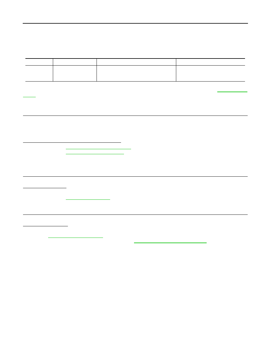
DTC
Trouble diagnosis name
DTC detecting condition
Possible causes
U0416
VDC CHECKSUM DI-
AGNOSIS
If camera control unit detects an error signal
that is received from ABS actuator and electric
unit (control unit) via CAN communication
ABS actuator and electric unit (control
unit)