содержание .. 288 289 290 291 ..
Nissan Murano. Manual - part 290
DAS-50
< BASIC INSPECTION >
[LDW]
ACTION TEST
NOTE:
After the operating conditions of warning are satisfied, the warning continues until the vehicle speed
reaches approximately 60 km/h (40 MPH). Refer to
>> INSPECTION END
Approx. 70
km/h (45
MPH) or more
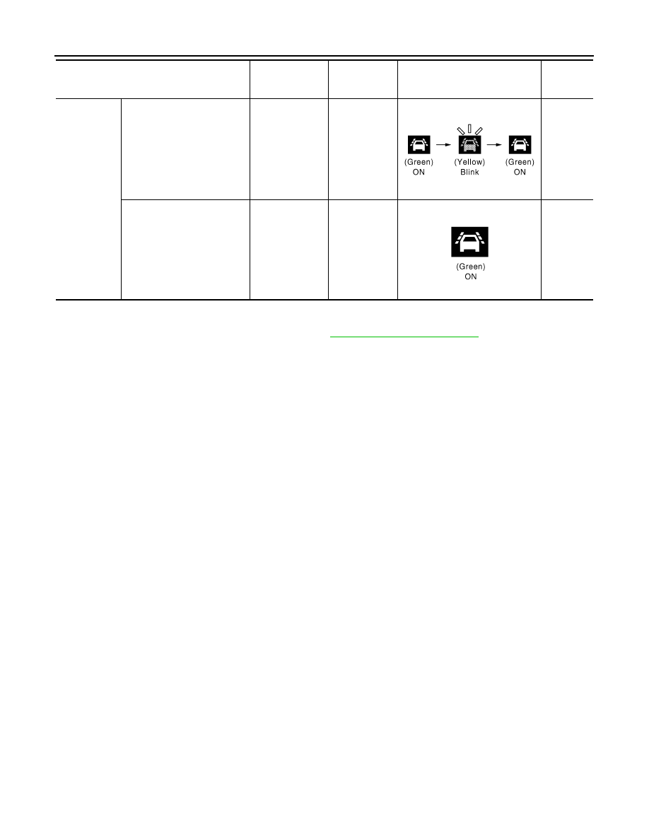
Close to lane marker
Warning
• Buzzer sounds
• Warning lamp
blinks
ON
Short con-
tinuous
beeps
• Close to lane marker
• Turn signal ON (Deviate
side)
No action
ON
—
Vehicle condition/ Driver's operation
Action
Warning sys-
tems ON indi-
cator
Indication on the combination
meter
Buzzer
JPOIA0022GB
JPOIA0021GB