содержание .. 234 235 236 237 ..
Nissan Murano. Manual - part 236
BRC-100
< DTC/CIRCUIT DIAGNOSIS >
[VDC/TCS/ABS]
VDC OFF INDICATOR LAMP
VDC OFF INDICATOR LAMP
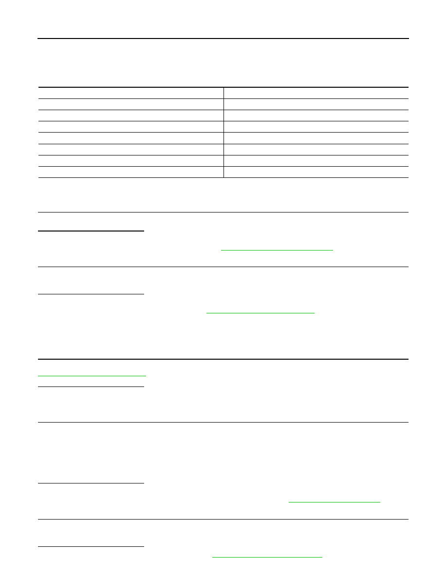
Description
INFOID:0000000009718353
×
: ON –: OFF
Component Function Check
INFOID:0000000009718354
1.
VDC OFF INDICATOR LAMP OPERATION CHECK 1
Check that the lamp illuminates for approximately 2 seconds after the ignition switch is turned ON.
Is the inspection result normal?
YES
>> GO TO 2.
NO
>> Proceed to diagnosis procedure. Refer to
BRC-100, "Diagnosis Procedure"
.
2.
VDC OFF INDICATOR LAMP OPERATION CHECK 2
Check that the VDC OFF indicator lamp in the combination meter turns ON/OFF correctly when operating the
VDC OFF switch.
Is the inspection result normal?
YES
>> INSPECTION END
NO
>> Check the VDC OFF switch. Refer to
Diagnosis Procedure
INFOID:0000000009718355
1.
CHECK ABS ACTUATOR AND ELECTRIC UNIT (CONTROL UNIT) POWER SUPPLY AND GROUND CIR-
CUIT
Perform diagnosis of ABS actuator and electric unit (control unit) power supply and ground circuit. Refer to
Is the inspection result normal?
YES
>> GO TO 2.
NO
>> Repair or replace error-detected parts.
2.
CHECK VDC OFF INDICATOR LAMP SIGNAL (1)
1.
Select “ABS”, “DATA MONITOR” and “OFF LAMP” according to this order with CONSULT.
2.
Turn the ignition switch OFF.
3.
Check that data monitor displays “On” for approx. 1 second after ignition switch is turned ON, and then
changes to “Off”.
CAUTION:
Never start engine.
Is the inspection result normal?
YES
>> GO TO 3.
NO
>> Replace ABS actuator and electric unit (control unit). Refer to
3.
CHECK VDC OFF INDICATOR LAMP SIGNAL (2)
1.
Select “ABS”, “DATA MONITOR” and “OFF LAMP” according to this order with CONSULT.
2.
Check that data monitor displays “On” or “Off” each time when VDC OFF switch is operated.
Is the inspection result normal?
YES
>> Check the combination meter. Refer to
MWI-34, "Diagnosis Description"
.
Condition
VDC OFF indicator lamp
Ignition switch OFF
–
For 2 seconds after turning ignition switch ON
×
2 seconds later after turning ignition switch ON
–
VDC OFF switch turned ON. (VDC function is OFF.)
×
VDC/TCS function is malfunctioning.
–
ABS function is malfunctioning.
–
EBD function is malfunctioning.
–