Nissan Murano. Manual - part 234


  Главная      Nissan     Nissan Murano (2014 year) - Service Manual


поиск по сайту            


содержание   ..  232  233  234  235   ..


Nissan Murano. Manual - part 234


BRC-92

< DTC/CIRCUIT DIAGNOSIS >

[VDC/TCS/ABS]

PARKING BRAKE SWITCH

PARKING BRAKE SWITCH

Component Function Check

INFOID:0000000009718333

1.

CHECK PARKING BRAKE SWITCH OPERATION

Operate the parking brake pedal. Then check that the brake warning lamp in the combination meter turns ON/
OFF correctly.

Is the inspection result normal?

YES

>> INSPECTION END

NO

>> Proceed to diagnosis procedure. Refer to 

BRC-92, "Diagnosis Procedure"

.

Diagnosis Procedure

INFOID:0000000009718334

1.

CHECK PARKING BRAKE SWITCH

Check the parking brake switch. Refer to 

BRC-92, "Component Inspection"

.

Is the inspection result normal?

YES

>> GO TO 2.

NO

>> Replace parking brake switch. Refer to 

PB-6, "Exploded View"

.

2.

CHECK COMBINATION METER

Check the indication and operation of combination meter are normal. Refer to 

MWI-34, "Diagnosis Descrip-

tion"

.

Is the inspection result normal?

YES

>> GO TO 3.

NO

>> Check the combination meter. Refer to 

MWI-35, "CONSULT Function (METER/M&A)"

.

3.

CHECK PARKING BRAKE SWITCH CIRCUIT

1.

Turn the ignition switch OFF.

2.

Disconnect parking brake switch harness connector.

3.

Disconnect combination meter harness connector.

4.

Check the continuity between parking brake switch harness connector and combination meter harness
connector.

Is the inspection result normal?

YES

>> INSPECTION END

NO

>> Repair or replace error-detected parts.

Component Inspection

INFOID:0000000009718335
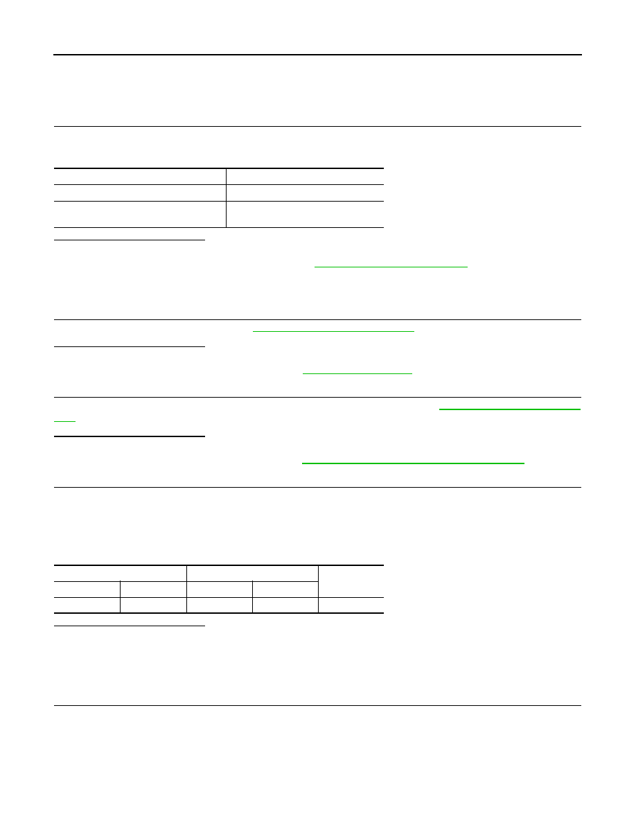
1.

CHECK PARKING BRAKE SWITCH

1.

Turn the ignition switch OFF.

2.

Disconnect parking brake switch harness connector.

3.

Check the continuity between parking brake switch connector terminal and ground.

Condition

Brake warning lamp illumination status

When the parking brake pedal is operation

ON

When the parking brake pedal is not oper-
ation.

OFF

Parking brake switch

Combination meter

Continuity

Connector

Terminal

Connector

Terminal

E27

1

M34

26

Existed

PARKING BRAKE SWITCH

BRC-93

< DTC/CIRCUIT DIAGNOSIS >

[VDC/TCS/ABS]

C

D

E

G

H

I

J

K

L

M

A

B

BRC

N

O

P

Is the inspection result normal?

YES

>> INSPECTION END

NO

>> Replace parking brake switch. Refer to 

PB-6, "Exploded View"

.

Parking brake switch

Condition

Continuity

Connector

Terminal

E27

1

Ground

When the parking brake switch 
is operated.

Existed

When the parking brake switch 
is not operated.

Not existed

BRC-94

< DTC/CIRCUIT DIAGNOSIS >

[VDC/TCS/ABS]

VDC OFF SWITCH

VDC OFF SWITCH

Description

INFOID:0000000009718336

VDC OFF switch can deactivate (turn OFF) the VDC/TCS function by pressing the VDC OFF switch.

Component Function Check

INFOID:0000000009718337

1.

CHECK VDC OFF SWITCH OPERATION

Turn ON/OFF the VDC OFF switch and check that the VDC OFF indicator lamp in the combination meter turns
ON/OFF correctly.
Is the inspection result normal?

YES

>> INSPECTION END

NO

>> Proceed to diagnosis procedure. Refer to 

BRC-94, "Diagnosis Procedure"

.

Diagnosis Procedure

INFOID:0000000009718338

1.

CHECK VDC OFF SWITCH

Check the VDC OFF switch. Refer to 

BRC-95, "Component Inspection"

.

Is the inspection result normal?

YES

>> GO TO 2.

NO

>> Replace VDC OFF switch. Refer to 

BRC-131, "Removal and Installation"

.

2.

CHECK VDC OFF SWITCH HARNESS

1.

Disconnect ABS actuator and electric unit (control unit) harness connector.

2.

Disconnect VDC OFF switch harness connector.

3.

Check the continuity between VDC OFF switch harness connector and ABS actuator and electric unit
(control unit) harness connector.

4.

Check the continuity between ABS actuator and electric unit (control unit) harness connector and ground.

5.

Check the continuity between VDC OFF switch harness connector and ground.

Is the inspection result normal?

YES

>> GO TO 3.

NO

>> Repair or replace error-detected parts.

3.

CHECK COMBINATION METER

1.

Connect ABS actuator and electric unit (control unit) harness connector.

2.

Connect VDC OFF switch harness connector.

3.

Check the indication and operation of combination meter are normal. Refer to 

MWI-34, "Diagnosis

Description"

.

Is the inspection result normal?

YES

>> INSPECTION END

ABS actuator and electric unit 

(control unit)

VDC OFF switch

Continuity

Connector

Terminal

Connector

Terminal

E36

22

M5

1

Existed

ABS actuator and electric unit (control unit)

Continuity

Connector

Terminal

E36

22

Ground

Not existed

VDC OFF switch

Continuity

Connector

Terminal

M5

2

Ground

Existed

VDC OFF SWITCH

BRC-95

< DTC/CIRCUIT DIAGNOSIS >

[VDC/TCS/ABS]

C

D

E

G

H

I

J

K

L

M

A

B

BRC

N

O

P

NO

>> Repair or replace combination meter.

Component Inspection

INFOID:0000000009718339

1.

CHECK VDC OFF SWITCH

1.

Turn the ignition switch OFF.

2.

Disconnect VDC OFF switch harness connector.

3.

Check the continuity between VDC OFF switch connector terminals.

Is the inspection result normal?

YES

>> INSPECTION END

NO

>> Replace VDC OFF switch. Refer to 

BRC-131, "Removal and Installation"

.

Special Repair Requirement

INFOID:0000000009718340

1.

ADJUSTMENT OF STEERING ANGLE SENSOR NEUTRAL POSITION AND CALIBRATION OF DECEL G

SENSOR

• After replacing an ABS actuator and electric unit (control unit), be sure to perform the following procedure.
- Adjustment of steering angle sensor neutral position: Refer to 

BRC-9, "ADJUSTMENT OF STEERING

ANGLE SENSOR NEUTRAL POSITION : Description"

.

- Calibration of decel G sensor: Refer to 

BRC-10, "CALIBRATION OF DECEL G SENSOR : Description"

.

• After removing an ABS actuator and electric unit (control unit), be sure to perform the following procedure.
- Calibration of decel G sensor: Refer to 

BRC-10, "CALIBRATION OF DECEL G SENSOR : Description"

.

• After removing/replacing a steering angle sensor, be sure to perform the following procedure.
- Adjustment of steering angle sensor neutral position: Refer to 

BRC-9, "ADJUSTMENT OF STEERING

ANGLE SENSOR NEUTRAL POSITION : Description"

.

• After removing/replacing a yaw rate/side/decel G sensor, be sure to perform the following procedure.
- Calibration of decel G sensor: Refer to 

BRC-10, "CALIBRATION OF DECEL G SENSOR : Description"

.

>> END

VDC OFF switch

Condition

Condition

Terminal

1 – 2

When VDC OFF switch is hold pressed.

Existed

When releasing VDC OFF switch.

Not existed


содержание   ..  232  233  234  235   ..