содержание .. 233 234 235 236 ..
Nissan Murano. Manual - part 235
BRC-96
< DTC/CIRCUIT DIAGNOSIS >
[VDC/TCS/ABS]
ABS WARNING LAMP
ABS WARNING LAMP
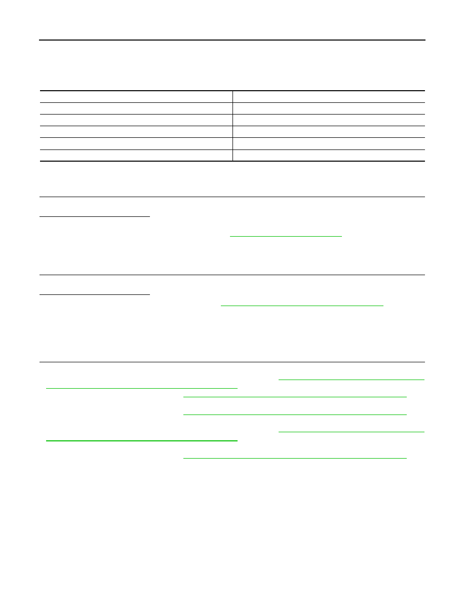
Description
INFOID:0000000009718341
×
: ON –: OFF
Component Function Check
INFOID:0000000009718342
1.
CHECK ABS WARNING LAMP OPERATION
Check that the lamp illuminates for approximately 2 seconds after the ignition switch is turned ON.
Is the inspection result normal?
YES
>> INSPECTION END
NO
>> Proceed to diagnosis procedure. Refer to
.
Diagnosis Procedure
INFOID:0000000009718343
1.
PERFORM SELF-DIAGNOSIS
Perform self-diagnosis for “ABS” with CONSULT.
Is the inspection result normal?
YES
>> Check the combination meter. Refer to
MWI-35, "CONSULT Function (METER/M&A)"
NO
>> Check items displayed by self-diagnosis for “ABS” with CONSULT.
Special Repair Requirement
INFOID:0000000009718344
1.
ADJUSTMENT OF STEERING ANGLE SENSOR NEUTRAL POSITION AND CALIBRATION OF DECEL G
SENSOR
• After replacing an ABS actuator and electric unit (control unit), be sure to perform the following procedure.
- Adjustment of steering angle sensor neutral position: Refer to
BRC-9, "ADJUSTMENT OF STEERING
ANGLE SENSOR NEUTRAL POSITION : Description"
.
- Calibration of decel G sensor: Refer to
BRC-10, "CALIBRATION OF DECEL G SENSOR : Description"
.
• After removing an ABS actuator and electric unit (control unit), be sure to perform the following procedure.
- Calibration of decel G sensor: Refer to
BRC-10, "CALIBRATION OF DECEL G SENSOR : Description"
.
• After removing/replacing a steering angle sensor, be sure to perform the following procedure.
- Adjustment of steering angle sensor neutral position: Refer to
BRC-9, "ADJUSTMENT OF STEERING
ANGLE SENSOR NEUTRAL POSITION : Description"
.
• After removing/replacing a yaw rate/side/decel G sensor, be sure to perform the following procedure.
- Calibration of decel G sensor: Refer to
BRC-10, "CALIBRATION OF DECEL G SENSOR : Description"
.
>> END
Condition
ABS warning lamp
Ignition switch OFF
–
For 2 seconds after turning ignition switch ON
×
2 seconds later after turning ignition switch ON (system is normal)
–
ABS function is malfunctioning.
×
EBD function is malfunctioning.
×