содержание .. 224 225 226 227 ..
Nissan Murano. Manual - part 226
BRC-60
< DTC/CIRCUIT DIAGNOSIS >
[VDC/TCS/ABS]
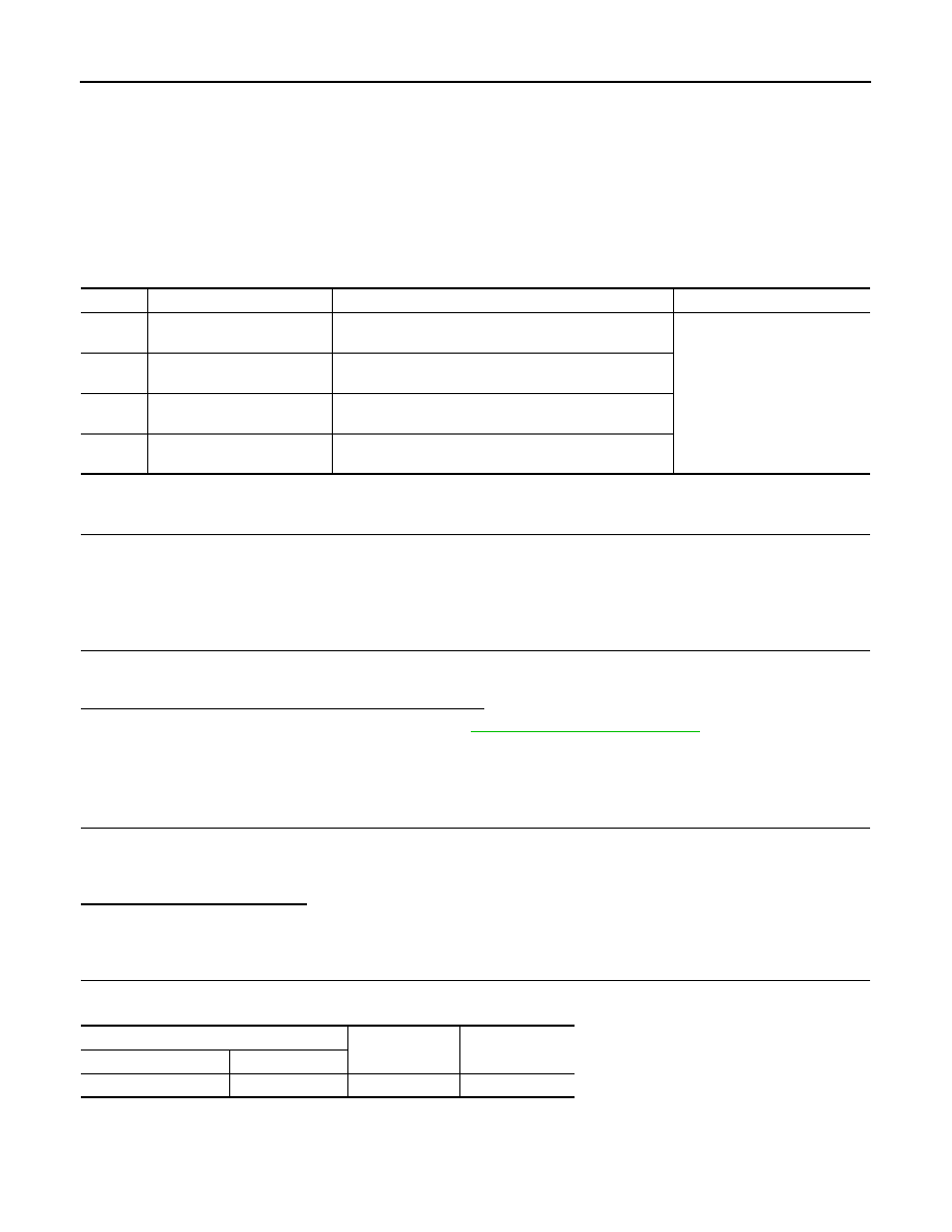
C1121, C1123, C1125, C1127 OUT ABS SOL
C1121, C1123, C1125, C1127 OUT ABS SOL
Description
INFOID:0000000009718273
The ABS OUT valve increases, holds or decreases the fluid pressure of each brake caliper according to the
signals transmitted by the ABS actuator and electric unit (control unit).
DTC Logic
INFOID:0000000009718274
DTC DETECTION LOGIC
DTC CONFIRMATION PROCEDURE
1.
PRECONDITIONING
If “DTC CONFIRMATION PROCEDURE” has been previously conducted, always turn the ignition switch OFF
and wait at least 10 seconds before conducting the next test.
>> GO TO 2.
2.
DTC REPRODUCTION PROCEDURE
1.
Turn the ignition switch OFF to ON.
2.
Perform self-diagnosis for “ABS” with CONSULT.
Is DTC “C1121”, “C1123”, “C1125” or “C1127” detected?
YES
>> Proceed to diagnosis procedure. Refer to
.
NO
>> INSPECTION END
Diagnosis Procedure
INFOID:0000000009718275
1.
CHECK CONNECTOR
1.
Turn the ignition switch OFF.
2.
Disconnect ABS actuator and electric unit (control unit) harness connector.
3.
Check the terminal for deformation, disconnection, looseness, etc.
Is the inspection result normal?
YES
>> GO TO 2.
NO
>> Repair or replace error-detected parts.
2.
CHECK ABS OUT VALVE POWER SUPPLY
1.
Check the voltage between ABS actuator and electric unit (control unit) harness connector and ground.
2.
Turn the ignition switch ON.
CAUTION:
Never start the engine.
3.
Check the voltage between ABS actuator and electric unit (control unit) harness connector and ground.
DTC
Display item
Malfunction detected condition
Possible cause
C1121
FR LH OUT ABS SOL
When the control unit detects a malfunction in the front
LH ABS OUT valve circuit.
• Harness or connector
• ABS actuator and electric unit
(control unit)
C1123
FR RH OUT ABS SOL
When the control unit detects a malfunction in the front
RH ABS OUT valve circuit.
C1125
RR LH OUT ABS SOL
When the control unit detects a malfunction in the rear LH
ABS OUT valve circuit.
C1127
RR RH OUT ABS SOL
When the control unit detects a malfunction in the rear
RH ABS OUT valve circuit.
ABS actuator and electric unit (control unit)
—
Voltage
(Approx.)
Connector
Terminal
E36
1
Ground
Battery voltage