Nissan Murano. Manual - part 202


  Главная      Nissan     Nissan Murano (2014 year) - Service Manual


поиск по сайту            


содержание   ..  200  201  202  203   ..


Nissan Murano. Manual - part 202


BR-18

< PERIODIC MAINTENANCE >

REAR DISC BRAKE

REAR DISC BRAKE

BRAKE PAD

BRAKE PAD : Inspection and Adjustment

INFOID:0000000009722311
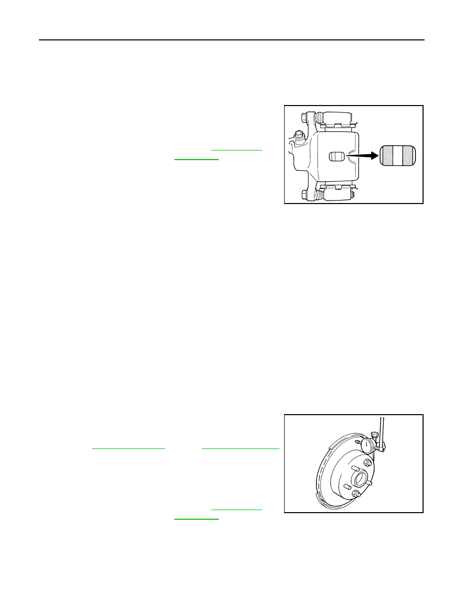
INSPECTION

Check brake pad wear thickness from an inspection hole on cylinder
body. Check using a scale if necessary. 

ADJUSTMENT

CAUTION:

• Burnish contact surfaces between pads according to the following procedure after refinishing or

replacing pads, or if a soft pedal occurs at very low mileage.

• Be careful of vehicle speed because the brake does not operate firmly/securely until pads and disc

rotor are securely fitted.

• Only perform this procedure under safe road and traffic conditions. Use extreme caution.
1.

Drive vehicle on straight, flat road.

2.

Depress brake pedal with the power to stop vehicle within 3 to 5 seconds until the vehicle stops.

3.

Drive without depressing brake for a few minutes to cool the brake.

4.

Repeat steps 1 to 3 until pad and disc rotor are securely fitted.

DISC ROTOR

DISC ROTOR : Inspection and Adjustment

INFOID:0000000009722312

INSPECTION

Appearance

Check surface of disc rotor for uneven wear, cracks, and serious damage. Replace if there are any abnormal
conditions.

Runout

1.

Fix the disc rotor to the wheel hub and bearing assembly with
wheel nuts (2 points at least).

2.

Check the wheel bearing axial end play before the inspection.
Refer to 

RAX-6, "Inspection"

 (2WD), 

RAX-13, "Inspection"

(AWD).   

3.

Inspect the runout with a dial gauge to measured at 10 mm (0.39
in) inside the disc edge.

4.

Find the installation position with a minimum runout by shifting the disc rotor-to-wheel hub and bearing
assembly installation position by one hole at a time if the runout exceeds the limit value.

5.

Refinish the disc rotor if the runout is outside the limit even after performing the above operation. [When
refinishing, use the Pro-Cut PEM On-Car brake Lathe (Tool No. 38-PFM90.5) or equivalent.]

CAUTION:

Limit

Wear thickness

: Refer to 

BR-54, "Rear 

Disc Brake"

.

BRA0010D

Limit

Runout

: Refer to 

BR-54, "Rear 

Disc Brake"

.

SBR019B

REAR DISC BRAKE

BR-19

< PERIODIC MAINTENANCE >

C

D

E

G

H

I

J

K

L

M

A

B

BR

N

O

P

• Check in advance that the thickness of the disc rotor is wear thickness + 0.3 mm (0.012 in) or

more.

• If the thickness is less than wear thickness + 0.3 mm (0.012 in), replace the disc rotor.

Thickness

Check the thickness of the disc rotor using a micrometer. Replace
the disc rotor if the thickness is below the wear limit. 

ADJUSTMENT

CAUTION:

• Burnish contact surfaces between pads according to the following procedure after refinishing or

replacing pads, or if a soft pedal occurs at very low mileage.

• Be careful of vehicle speed because the brake does not operate firmly/securely until pads and disc

rotor are securely fitted.

• Only perform this procedure under safe road and traffic conditions. Use extreme caution.

1.

Drive vehicle on straight, flat road.

2.

Depress brake pedal with the power to stop vehicle within 3 to 5 seconds until the vehicle stops.

3.

Drive without depressing brake for a few minutes to cool the brake.

4.

Repeat steps 1 to 3 until pad and disc rotor are securely fitted.

Limit

Wear thickness

: Refer to 

BR-54, "Rear Disc Brake"

.

Limit

Wear thickness

: Refer to 

BR-54, "Rear 

Disc Brake"

.

Thickness variation

: Refer to 

BR-54, "Rear 

Disc Brake"

.

SBR020B

BR-20

< REMOVAL AND INSTALLATION >

BRAKE PEDAL

REMOVAL AND INSTALLATION

BRAKE PEDAL

Exploded View

INFOID:0000000009722313

Removal and Installation

INFOID:0000000009722314

REMOVAL

1.

Remove instrument lower panel LH. Refer to 

IP-14, "Exploded View"

.

2.

Remove knee protector.
• With heated steering wheel (without electric motor): Refer to 

ST-37, "WITHOUT ELECTRIC MOTOR :

Removal and Installation"

.

• With heated steering wheel (with electric motor): Refer to 

ST-40, "WITH ELECTRIC MOTOR : Removal

and Installation"

.

• Without heated steering wheel: Refer to 

ST-82, "Removal and Installation"

.

3.

Disconnect the stop lamp switch and ASCD brake switch harness connectors.

4.

Remove snap pin and clevis pin from clevis of brake booster.

5.

Remove the brake pedal assembly.

CAUTION:

Hold the brake booster and master cylinder so as not to drop out or contact them to other parts.

INSTALLATION

Note the following, and install the reverse order of removal.

1.

Clevis pin

2.

Brake pedal assembly

3.

Brake pedal pad

4.

ASCD brake switch

5.

Stop lamp switch

6.

Clip

7.

Snap pin

: Apply multi-purpose grease.

Refer to 

GI-4, "Components"

 for symbols not described on the above.

JPFIA0440GB

BRAKE PEDAL

BR-21

< REMOVAL AND INSTALLATION >

C

D

E

G

H

I

J

K

L

M

A

B

BR

N

O

P

• Apply the multi-purpose grease to the clevis pin and the mating faces. (Not necessary if grease has been

already applied.)

NOTE:
The clevis pin may be inserted in either direction.

Inspection and Adjustment

INFOID:0000000009722315

INSPECTION AFTER REMOVAL

• Check the following items and replace the brake pedal assembly if

necessary.

- Check the brake pedal upper rivet (made by aluminum) (A) for

deformation.

- Check the brake pedal for bend, damage, and cracks on the

welded parts.

- Check the lapping length (X) of sub-bracket (B) and slide plate (C).

• Check clevis pin and plastic stopper (A) for damage and deforma-

tion. If any damage is found, replace clevis pin.

ADJUSTMENT AFTER INSTALLATION

Perform the brake pedal adjustment after installing the brake pedal assembly. Refer to 

BR-9, "Inspection and

Adjustment"

.

Standard

X

: 5.0 mm (0.197 in) or more

JPFIA0300ZZ

PFIA0756J


содержание   ..  200  201  202  203   ..