Nissan Murano. Manual - part 200


  Главная      Nissan     Nissan Murano (2014 year) - Service Manual


поиск по сайту            


содержание   ..  198  199  200  201   ..


Nissan Murano. Manual - part 200


BR-10

< PERIODIC MAINTENANCE >

BRAKE PEDAL

ADJUSTMENT

Brake Pedal Height

1.

Remove instrument lower panel LH. Refer to 

IP-14, "Exploded View"

.

2.

Disconnect the stop lamp switch and ASCD brake switch harness connector.

3.

Turn the stop lamp switch and ASCD brake switch 45

°

 counterclockwise.

4.

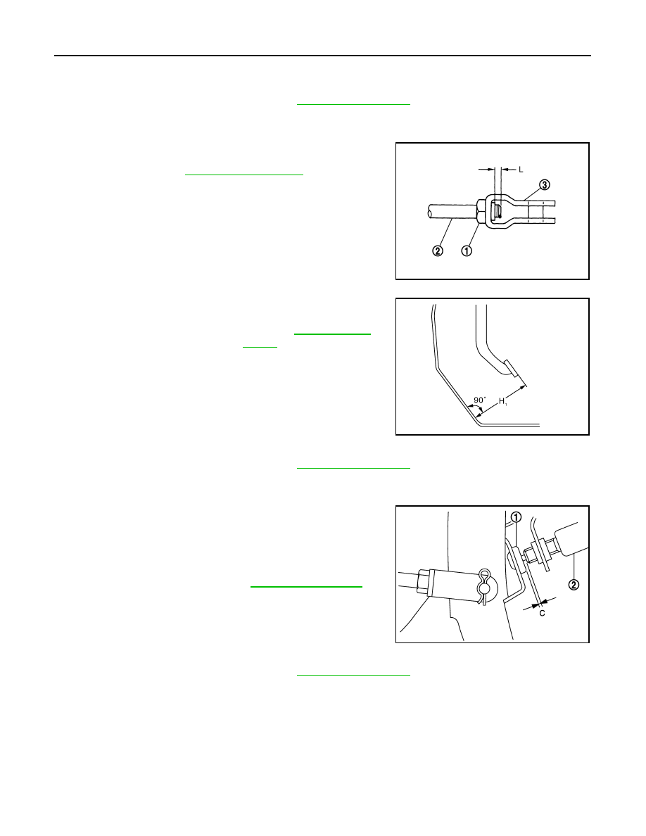
Loosen the input rod lock nut (1). Adjust the brake pedal height
(H

1

) to the specification. Tighten the input rod lock nut to the

specification. Refer to 

BR-30, "Exploded View"

.

CAUTION:

The threaded end of the input rod (2) must project to the
inner side (L) of the clevis (3).

Stop Lamp Switch and ASCD Brake Switch

1.

Remove instrument lower panel LH. Refer to 

IP-14, "Exploded View"

.

2.

Disconnect the stop lamp switch and ASCD brake switch harness connector.

3.

Turn the stop lamp switch and ASCD brake switch 45

°

 counterclockwise.

4.

Press-fit stop lamp switch and ASCD brake switch (2) until stop
lamp switch and ASCD brake switch hits the stopper rubber (1)
45

°

 clockwise.

CAUTION:

• The clearance (C) between the stopper rubber and stop

lamp switch and ASCD brake switch threaded end must
be the specified value. Refer to 

BR-53, "Brake Pedal"

• The stop lamp must be turned off when the brake pedal is

released.

Brake Pedal Play

1.

Remove instrument lower panel LH. Refer to 

IP-14, "Exploded View"

.

2.

Disconnect the stop lamp switch and ASCD brake switch harness connector.

3.

Turn the stop lamp switch and ASCD brake switch 45

°

 counterclockwise.

JPFIA0003ZZ

Standard

H

1

: Refer to 

BR-53, "Brake 

Pedal"

.

JPFIA0279ZZ

JPFIA0122ZZ

BRAKE PEDAL

BR-11

< PERIODIC MAINTENANCE >

C

D

E

G

H

I

J

K

L

M

A

B

BR

N

O

P

4.

Press-fit stop lamp switch and ASCD brake switch (2) until stop
lamp switch and ASCD brake switch hits the stopper rubber (1)
45

°

 clockwise.

CAUTION:

• The clearance (C) between the stopper rubber and stop

lamp switch and ASCD brake switch threaded end must
be the specified value. Refer to 

BR-53, "Brake Pedal"

• The stop lamp must be turned off when the brake pedal is

released.

JPFIA0122ZZ

BR-12

< PERIODIC MAINTENANCE >

BRAKE FLUID

BRAKE FLUID

Inspection

INFOID:0000000009722303

BRAKE FLUID LEVEL

• Check that the fluid level in the sub tank is within the specified

range (MAX – MIN lines).

• Visually check for any brake fluid leakage around the sub tank,

reservoir tank and hose.

• Check the brake system for any leakage if the fluid level is

extremely low (lower than MIN).

• Check the brake system for fluid leakage if the warning lamp

remains illuminated even after the parking brake is released.

BRAKE LINE

1.

Check brake line (tubes and hoses) for cracks, deterioration or other damage. Replace any damaged
parts.

2.

Check for fluid leakage by fully depressing brake pedal while
engine is running.

CAUTION:

If leakage occurs around joints, retighten or, if necessary,
replace damaged parts.

Draining

INFOID:0000000009722304

CAUTION:

• Never spill or splash brake fluid on painted surfaces. Brake fluid may seriously damage paint. Wipe it

off immediately and wash with water if it gets on a painted surface.

• Turn the ignition switch OFF and disconnect the ABS actuator and electric unit (control unit) con-

nector or the battery negative terminal before draining.

1.

Connect a vinyl tube to the bleed valve.

2.

Depress the brake pedal and loosen the bleeder valve to gradu-
ally discharge brake fluid.

Refilling

INFOID:0000000009722305

CAUTION:

Turn the ignition switch OFF and disconnect the ABS actuator and electric unit (control unit) connec-
tor or the battery negative terminal before refilling.

1.

Check that there is no foreign material in the sub tank, and refill with new brake fluid.

CAUTION:

Never reuse drained brake fluid.

JPFIA0295ZZ

SBR389C

BRA0007D

BRAKE FLUID

BR-13

< PERIODIC MAINTENANCE >

C

D

E

G

H

I

J

K

L

M

A

B

BR

N

O

P

2.

Loosen the bleeder valve, slowly depress the brake pedal to the full stroke, and then release the pedal.
Repeat this operation at intervals of 2 or 3 seconds until all brake fluid is discharged. Then close the
bleeder valve with the brake pedal depressed. Repeat the same work on each wheel.

3.

Perform the air bleeding. Refer to 

BR-13, "Bleeding Brake System"

.

Bleeding Brake System

INFOID:0000000009722306

CAUTION:

• Turn the ignition switch OFF and disconnect the ABS actuator and electric unit (control unit) con-

nector or the battery negative terminal before performing the work.

• Monitor the fluid level in the sub tank during the air bleeding.
• Always use new brake fluid for refilling. Never reuse the drained brake fluid.

1.

Connect a vinyl tube to the bleeder valve of the rear right brake.

2.

Fully depress the brake pedal 4 to 5 times.

3.

Loosen the bleeder valve and bleed air with the brake pedal depressed, and then quickly tighten the
bleeder valve.

4.

Repeat steps 2 and 3 until all of the air is out of the brake line.

5.

Tighten the bleeder valve to the specified torque.
• Front disc brake
- 1 piston type: Refer to 

BR-38, "BRAKE CALIPER ASSEMBLY (1 PISTON TYPE) : Exploded View"

.

- 2 piston type: Refer to 

BR-42, "BRAKE CALIPER ASSEMBLY (2 PISTON TYPE) : Exploded View"

.

• Rear disc brake: Refer to 

BR-48, "BRAKE CALIPER ASSEMBLY : Exploded View"

.

6.

Perform steps 1 to 5 for the rear right brake 

 front left brake 

 rear left brake 

 and front right brake in

order.

7.

Check that the fluid level in the sub tank is within the specified range after air bleeding. Refer to 

BR-9,

"Inspection and Adjustment"

.


содержание   ..  198  199  200  201   ..