содержание .. 197 198 199 200 ..
Nissan Murano. Manual - part 199
BR-6
< PRECAUTION >
PRECAUTIONS
• Never use electrical test equipment on any circuit related to the SRS unless instructed to in this Ser-
vice Manual. SRS wiring harnesses can be identified by yellow and/or orange harnesses or harness
connectors.
PRECAUTIONS WHEN USING POWER TOOLS (AIR OR ELECTRIC) AND HAMMERS
WARNING:
Always observe the following items for preventing accidental activation.
• When working near the Air Bag Diagnosis Sensor Unit or other Air Bag System sensors with the
ignition ON or engine running, never use air or electric power tools or strike near the sensor(s) with
a hammer. Heavy vibration could activate the sensor(s) and deploy the air bag(s), possibly causing
serious injury.
• When using air or electric power tools or hammers, always switch the ignition OFF, disconnect the
battery, and wait at least 3 minutes before performing any service.
FOR MEXICO : Precaution for Procedure without Cowl Top Cover
INFOID:0000000009722299
When performing the procedure after removing cowl top cover, cover
the lower end of windshield with urethane, etc to prevent damage to
windshield.
FOR MEXICO : Precaution for Brake System
INFOID:0000000009722300
WARNING:
Since dust covering the front and rear brakes has an affect on human body, the dust must be removed
with a dust collector. Never splatter the dust with an air blow gun.
CAUTION:
• Brake fluid use refer to
MA-16, "FOR MEXICO : Fluids and Lubricants"
.
• Never reuse drained brake fluid.
• Never spill or splash brake fluid on painted surfaces. Brake fluid may seriously damage paint. Wipe it
off immediately and wash with water if it gets on a painted surface.
• Always clean with new brake fluid when cleaning the master cylinder, brake caliper and other com-
ponents.
• Never use mineral oils such as gasoline or light oil to clean. They may damage rubber parts and
cause improper operation.
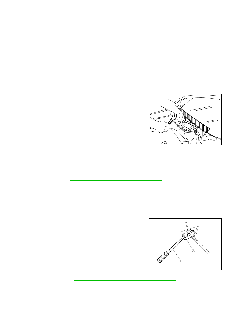
• Always loosen the brake tube flare nut with a flare nut wrench.
• Tighten the brake tube flare nut to the specified torque with
crowfoot (A) and torque wrench (B).
• Always confirm the specified tightening torque when install-
ing the brake pipes.
• Turn the ignition switch OFF and disconnect the ABS actuator
and electric unit (control unit) connector or the battery nega-
tive terminal before performing the work.
• Check that no brake fluid leakage is present after replacing
the parts.
• Burnish the brake contact surfaces after refinishing or replac-
ing rotors, after replacing pads, or if a soft pedal occurs at
very low mileage.
- Front brake pad: Refer to
BR-16, "BRAKE PAD : Inspection and Adjustment"
.
- Front disc rotor: Refer to
BR-16, "DISC ROTOR : Inspection and Adjustment"
- Rear brake pad: Refer to
BR-18, "BRAKE PAD : Inspection and Adjustment"
- Rear disc rotor: Refer to
BR-18, "DISC ROTOR : Inspection and Adjustment"
PIIB3706J
JPFIA0001ZZ