Nissan Murano. Manual - part 175


  Главная      Nissan     Nissan Murano (2014 year) - Service Manual


поиск по сайту            


содержание   ..  173  174  175  176   ..


Nissan Murano. Manual - part 175


BCS

BODY CONTROL SYSTEM

BCS-9

< SYSTEM DESCRIPTION >

C

D

E

F

G

H

I

J

K

L

B

A

O

P

N

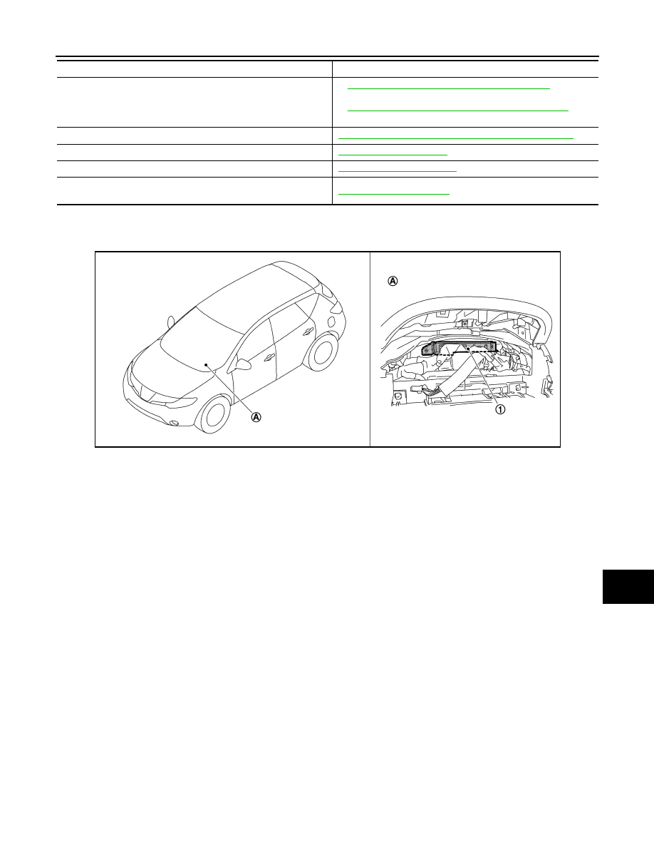
Component Parts Location

INFOID:0000000009722433

Rear window defogger system

DEF-4, "WITH BOSE SYSTEM : System Diagram"

 (With 

BOSE system)

DEF-6, "WITHOUT BOSE SYSTEM : System Diagram"

 (With-

out BOSE system)

Intelligent Key system/engine start system

DLK-18, "INTELLIGENT KEY SYSTEM : System Diagram"

Power window system

PWC-7, "System Diagram"

Retained accessory power (RAP) system

PWC-7, "System Description"

Tire pressure monitor system (TPMS) - AIR PRESSURE MONI-
TOR

WT-8, "System Description"

System

Reference

1.

BCM

A.

Behind of combination meter

JPMIA0897ZZ

BCS-10

< SYSTEM DESCRIPTION >

COMBINATION SWITCH READING SYSTEM

COMBINATION SWITCH READING SYSTEM

System Diagram

INFOID:0000000009722434

NOTE:
• *1: TAIL LAMP switch links lighting switch 1ST position.
• *2: “FR WIP INT/AT” is FR WIPER INT/AUTO.

System Description

INFOID:0000000009722435

OUTLINE

• BCM reads the status of the combination switch (light, turn signal, wiper and washer) and recognizes the

status of each switch.

• BCM is a combination of 5 output terminals (OUTPUT 1 - 5) and 5 input terminals (INPUT 1 - 5). It reads a

maximum of 20 switch status.

COMBINATION SWITCH MATRIX

Combination switch circuit

NOTE:
• *1: TAIL LAMP switch links lighting switch 1ST position.
• *2: “FR WIP INT/AT” is FR WIPER INT/AUTO.

JMMIA0292GB

JMMIA0293GB

BCS

COMBINATION SWITCH READING SYSTEM

BCS-11

< SYSTEM DESCRIPTION >

C

D

E

F

G

H

I

J

K

L

B

A

O

P

N

Combination switch INPUT-OUTPUT system list

NOTE:

Headlamp has a dual system switch.

COMBINATION SWITCH READING FUNCTION

Description

• BCM reads the status of the combination switch at 10 ms interval normally.

NOTE:
BCM reads the status of the combination switch at 60 ms interval when BCM is controlled at low power con-
sumption mode.

• BCM operates as follows and judges the status of the combination switch.
- INPUT 1 - 5 outputs the voltage waveforms of 5 systems simultaneously.
- It operates the transistor on OUTPUT side in the following order: OUTPUT 5 

 4 

 3 

 2 

 1.

- The voltage waveform of INPUT corresponding to the formed circuit changes according to the operation of

the transistor on OUTPUT side if any (1 or more) switches are ON.

- It reads this change of the voltage as the status signal of the combination switch.

System

OUTPUT 1

OUTPUT 2

OUTPUT 3

OUTPUT 4

OUTPUT 5

INPUT 1

FR WASHER

FR WIPER LOW

TURN LH

TURN RH

INPUT 2

FR WIPER HI

FR WIPER INT/

AUTO

PASSING

HEADLAMP 1

INPUT 3

WIP VOLUME 1

RR WASHER

HEADLAMP 2

HI BEAM

INPUT 4

RR WIPER INT

WIP VOLUME 3

AUTO LIGHT

TAIL LAMP

INPUT 5

WIP VOLUME 2

RR WIPER ON

FR FOG

JPMIA0067GB

JPMIA0068GB

BCS-12

< SYSTEM DESCRIPTION >

COMBINATION SWITCH READING SYSTEM

Operation Example

In the following operation example, the combination of the status signals of the combination switch is replaced
as follows: INPUT 1 - 5 to “1 - 5” and OUTPUT 1 - 5 to “A - E”.

Example 1: When a switch (TURN RH switch) is turned ON

• The circuit between INPUT 1 and OUTPUT 5 is formed when the TURN RH switch is turned ON.

• BCM detects the combination switch status signal “1E” when the signal of OUTPUT 5 is input to INPUT 1.
• BCM judges that the TURN RH switch is ON when the signal “1E” is detected.

Example 2: When some switches (turn RH switch, front wiper LO switch) are turned ON

• The circuits between INPUT 1 and OUTPUT 5 and between INPUT 1 and OUTPUT 3 are formed when the

TURN RH switch and FR WIPER LOW switch are turned ON.

• BCM detects the combination switch status signal “1CE” when the signals of OUTPUT 3 and OUTPUT 5 are

input to INPUT 1.

• BCM judges that the TURN RH switch and FR WIPER LOW switch are ON when the signal “1CE” is

detected.

WIPER VOLUME DIAL POSITION

BCM judges the wiper volume dial 1 - 7 by the status of WIP VOLUME 1, 2 and 3 switches.

JMMIA0294GB

JMMIA0295GB

Wiper volume dial position

Switch status  

WIP VOLUME 1

WIP VOLUME 2

WIP VOLUME 3

1

ON

ON

ON

2

ON

ON

OFF


содержание   ..  173  174  175  176   ..