содержание .. 1439 1440 1441 1442 ..
Nissan Murano. Manual - part 1441
VTL-120
< REMOVAL AND INSTALLATION >
[WITH 7 INCH DISPLAY]
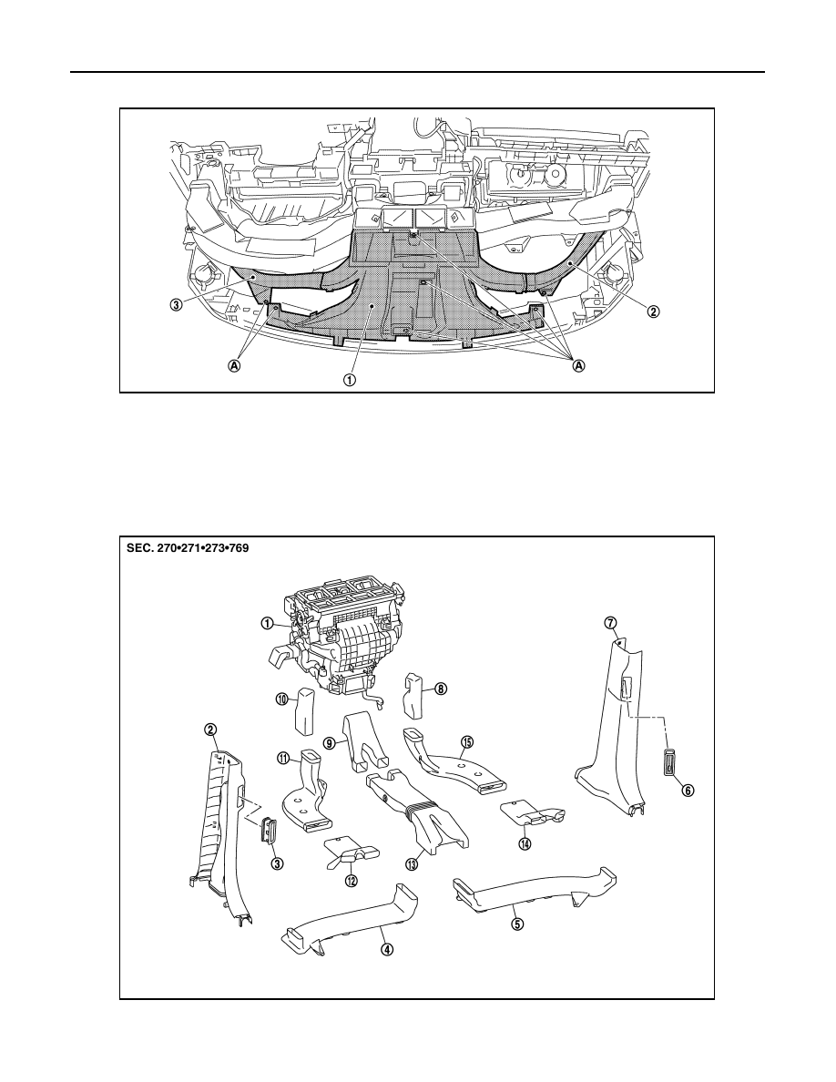
DUCT AND GRILLE
2.
Remove fixing screws (A) and then remove defroster nozzle (1) together with the side defroster nozzle RH
(2) and side defroster nozzle LH (3).
3.
Remove side defroster nozzle LH and RH from defroster nozzle.
INSTALLATION
Install in the reverse order of removal.
REAR VENTILATOR GRILLE
REAR VENTILATOR GRILLE : Exploded View
INFOID:0000000009721197
JPIIA0587ZZ
JPIIA0457ZZ