Nissan Murano. Manual - part 1442


  Главная      Nissan     Nissan Murano (2014 year) - Service Manual


поиск по сайту            


содержание   ..  1440  1441  1442  1443   ..


Nissan Murano. Manual - part 1442


VTL-124

< REMOVAL AND INSTALLATION >

[WITH 7 INCH DISPLAY]

DUCT AND GRILLE

INSTALLATION

Install in the reverse order of removal.

REAR VENTILATOR DUCT 3

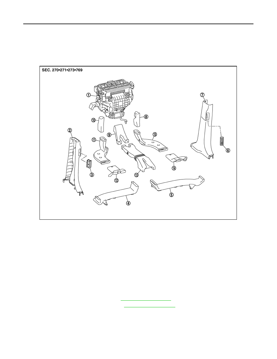
REAR VENTILATOR DUCT 3 : Exploded View

INFOID:0000000009721203

REAR VENTILATOR DUCT 3 : Removal and Installation

INFOID:0000000009721204

REMOVAL

Driver Side

1.

Remove front seat assembly LH. Refer to 

SE-92, "Exploded View"

2.

Pull up the driver side floor carpet. Refer to 

INT-24, "Exploded View"

1.

Heater & cooling unit assembly

2.

Rear ventilator duct 4
(Center pillar lower garnish LH)

3.

Rear ventilator grille LH

4.

Rear ventilator duct 3 LH

5.

Rear ventilator duct 3 RH

6.

Rear ventilator grille RH

7.

Rear ventilator duct 4
(Center pillar lower garnish RH)

8.

Rear foot duct 1 RH

9.

Rear ventilator duct 1

10.

Rear foot duct 1 LH

11.

Rear foot duct 2 LH

12.

Rear foot duct 3 LH

13.

Rear ventilator duct 2

14.

Rear foot duct 3 RH

15.

Rear foot duct 2 RH

JPIIA0457ZZ

DUCT AND GRILLE

VTL-125

< REMOVAL AND INSTALLATION >

[WITH 7 INCH DISPLAY]

C

D

E

F

G

H

J

K

L

M

A

B

VTL

N

O

P

3.

Remove fixing screws (A) and then remove rear ventilator duct 3
LH (1). 

Passenger side

1.

Remove front seat assembly RH. Refer to 

SE-92, "Exploded View"

2.

Pull up the passenger side floor carpet. Refer to 

INT-24, "Exploded View"

3.

Remove fixing screws (A) and then remove rear ventilator duct 3
RH (1). 

INSTALLATION

Install in the reverse order of removal.

REAR VENTILATOR DUCT 4

JPIIA0591ZZ

JPIIA0592ZZ

VTL-126

< REMOVAL AND INSTALLATION >

[WITH 7 INCH DISPLAY]

DUCT AND GRILLE

REAR VENTILATOR DUCT 4 : Exploded View

INFOID:0000000009721205

REAR VENTILATOR DUCT 4 : Removal and Installation

INFOID:0000000009721206

REMOVAL

Remove center pillar lower garnish. Refer to 

INT-20, "Exploded View"

INSTALLATION

Install in the reverse order of removal.

REAR FOOT DUCT 1

1.

Heater & cooling unit assembly

2.

Rear ventilator duct 4
(Center pillar lower garnish LH)

3.

Rear ventilator grille LH

4.

Rear ventilator duct 3 LH

5.

Rear ventilator duct 3 RH

6.

Rear ventilator grille RH

7.

Rear ventilator duct 4
(Center pillar lower garnish RH)

8.

Rear foot duct 1 RH

9.

Rear ventilator duct 1

10.

Rear foot duct 1 LH

11.

Rear foot duct 2 LH

12.

Rear foot duct 3 LH

13.

Rear ventilator duct 2

14.

Rear foot duct 3 RH

15.

Rear foot duct 2 RH

JPIIA0457ZZ

DUCT AND GRILLE

VTL-127

< REMOVAL AND INSTALLATION >

[WITH 7 INCH DISPLAY]

C

D

E

F

G

H

J

K

L

M

A

B

VTL

N

O

P

REAR FOOT DUCT 1 : Exploded View

INFOID:0000000009721207

REAR FOOT DUCT 1 : Removal and Installation

INFOID:0000000009721208

REMOVAL

Driver Side

1.

Remove instrument lower cover LH. Refer to 

IP-14, "Exploded View"

2.

Remove rear foot duct 1 LH (1). 

Passenger Side

1.

Heater & cooling unit assembly

2.

Rear ventilator duct 4
(Center pillar lower garnish LH)

3.

Rear ventilator grille LH

4.

Rear ventilator duct 3 LH

5.

Rear ventilator duct 3 RH

6.

Rear ventilator grille RH

7.

Rear ventilator duct 4
(Center pillar lower garnish RH)

8.

Rear foot duct 1 RH

9.

Rear ventilator duct 1

10.

Rear foot duct 1 LH

11.

Rear foot duct 2 LH

12.

Rear foot duct 3 LH

13.

Rear ventilator duct 2

14.

Rear foot duct 3 RH

15.

Rear foot duct 2 RH

JPIIA0457ZZ

JPIIA0595ZZ


содержание   ..  1440  1441  1442  1443   ..