содержание .. 1434 1435 1436 1437 ..
Nissan Murano. Manual - part 1436
VTL-100
< REMOVAL AND INSTALLATION >
[WITH 7 INCH DISPLAY]
HEATER & COOLING UNIT ASSEMBLY
HEATER & COOLING UNIT ASSEMBLY
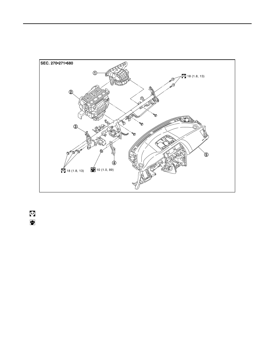
Exploded View
INFOID:0000000009721175
REMOVAL
DISASSEMBLY
1.
Blower unit assembly
2.
Heater & cooling unit assembly
3.
Steering member
4.
Instrument stay
5.
Instrument panel assembly
: N·m (kg-m, ft-lb)
: N·m (kg-m, in-lb)
JSIIA1794GB