Nissan Murano. Manual - part 1434


  Главная      Nissan     Nissan Murano (2014 year) - Service Manual


поиск по сайту            


содержание   ..  1432  1433  1434  1435   ..


Nissan Murano. Manual - part 1434


VTL-92

< REMOVAL AND INSTALLATION >

[WITH 7 INCH DISPLAY]

SUNLOAD SENSOR

SUNLOAD SENSOR

Exploded View

INFOID:0000000009721165

Removal and Installation

INFOID:0000000009721166
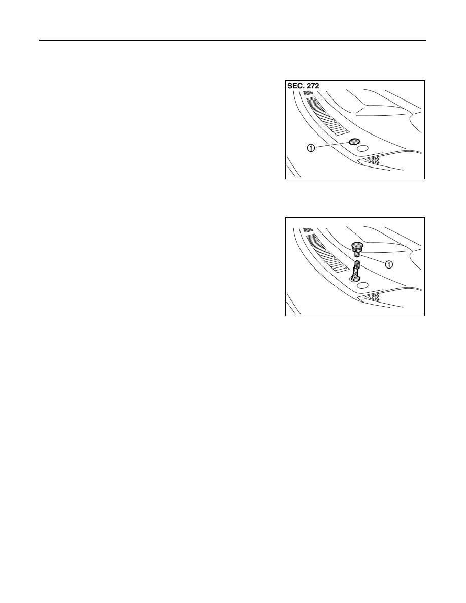
REMOVAL

Disconnect sunload sensor connector and then remove sunload
sensor (1). 

INSTALLATION

Install in the reverse order of removal.

1.

Sunload sensor

JPIIA0559ZZ

JPIIA0560ZZ

INTAKE SENSOR

VTL-93

< REMOVAL AND INSTALLATION >

[WITH 7 INCH DISPLAY]

C

D

E

F

G

H

J

K

L

M

A

B

VTL

N

O

P

INTAKE SENSOR

Exploded View

INFOID:0000000009721167

Removal and Installation

INFOID:0000000009721168

REMOVAL

1.

Remove evaporator pipe assembly. Refer to 

VTL-100, "Exploded View"

2.

Slide the evaporator (1) toward the right side of the vehicle and
then remove intake sensor (2).

INSTALLATION

Note the following items, and then install in the reverse order of removal.

CAUTION:

• Replace the O-ring with a new one. Apply a coat of compressor oil to the O-ring prior to installation. 
• Install the intake sensor in the same position as the removed intake sensor when replacing the

intake sensor. 

• Never rotate the bracket insertion part when removing and installing the intake sensor. 
• Check for refrigerant leakage when charging refrigerant.

1.

Heater & cooling unit assembly

2.

Intake sensor bracket

3.

Intake sensor

4.

Evaporator assembly

5.

Evaporator cover

6.

Air mix door motor (Passenger side)

7.

Foot duct RH

8.

Cooler pipe grommet

JPIIA1303ZZ

JPIIA0907ZZ

VTL-94

< REMOVAL AND INSTALLATION >

[WITH 7 INCH DISPLAY]

BLOWER UNIT

BLOWER UNIT

Exploded View

INFOID:0000000009721169

REMOVAL

DISASSEMBLY

1.

Blower unit assembly

2.

Heater & cooling unit assembly

3.

Steering member

4.

Instrument stay

5.

Instrument panel assembly

: N·m (kg-m, ft-lb)

: N·m (kg-m, in-lb)

JSIIA1794GB

BLOWER UNIT

VTL-95

< REMOVAL AND INSTALLATION >

[WITH 7 INCH DISPLAY]

C

D

E

F

G

H

J

K

L

M

A

B

VTL

N

O

P

Removal and Installation

INFOID:0000000009721170

REMOVAL

1.

Remove instrument panel assembly. Refer to 

IP-14, "Exploded View"

2.

Remove mounting nuts (A) and then remove instrument panel
stay (1). 

3.

Disconnect intake door motor and blower motor connectors. 

4.

Remove heater & cooling unit assembly and blower unit mounting bolts (A). 

1.

Shutter box case

2.

Intake door

3.

Intake door motor

4.

Blower motor assembly

5.

Intake lower case

6.

Outlet seal

7.

Intake seal

8.

Intake upper case

JPIIA0455ZZ

JPIIA0565ZZ


содержание   ..  1432  1433  1434  1435   ..