Nissan Murano. Manual - part 1375


  Главная      Nissan     Nissan Murano (2014 year) - Service Manual


поиск по сайту            


содержание   ..  1373  1374  1375  1376   ..


Nissan Murano. Manual - part 1375


TM-42

< DTC/CIRCUIT DIAGNOSIS >

[CVT: RE0F09B]

U0100 LOST COMMUNICATION (ECM A)

DTC/CIRCUIT DIAGNOSIS

U0100 LOST COMMUNICATION (ECM A)

DTC Logic

INFOID:0000000009719421

DTC DETECTION LOGIC

DTC CONFIRMATION PROCEDURE

1.

PREPARATION BEFORE WORK

If another “DTC CONFIRMATION PROCEDURE” occurs just before, turn ignition switch OFF and wait for at
least 10 seconds, then perform the next test.

>> GO TO 2.

2.

PERFORM DTC CONFIRMATION PROCEDURE

1.

Start the engine and wait for at least 5 seconds.

2.

Check the first trip DTC.

Is “U0100” detected?

YES

>> Go to 

TM-42, "Diagnosis Procedure"

.

NO

>> INSPECTION END

Diagnosis Procedure

INFOID:0000000009719422

For the diagnosis procedure, refer to 

LAN-18, "Trouble Diagnosis Flow Chart"
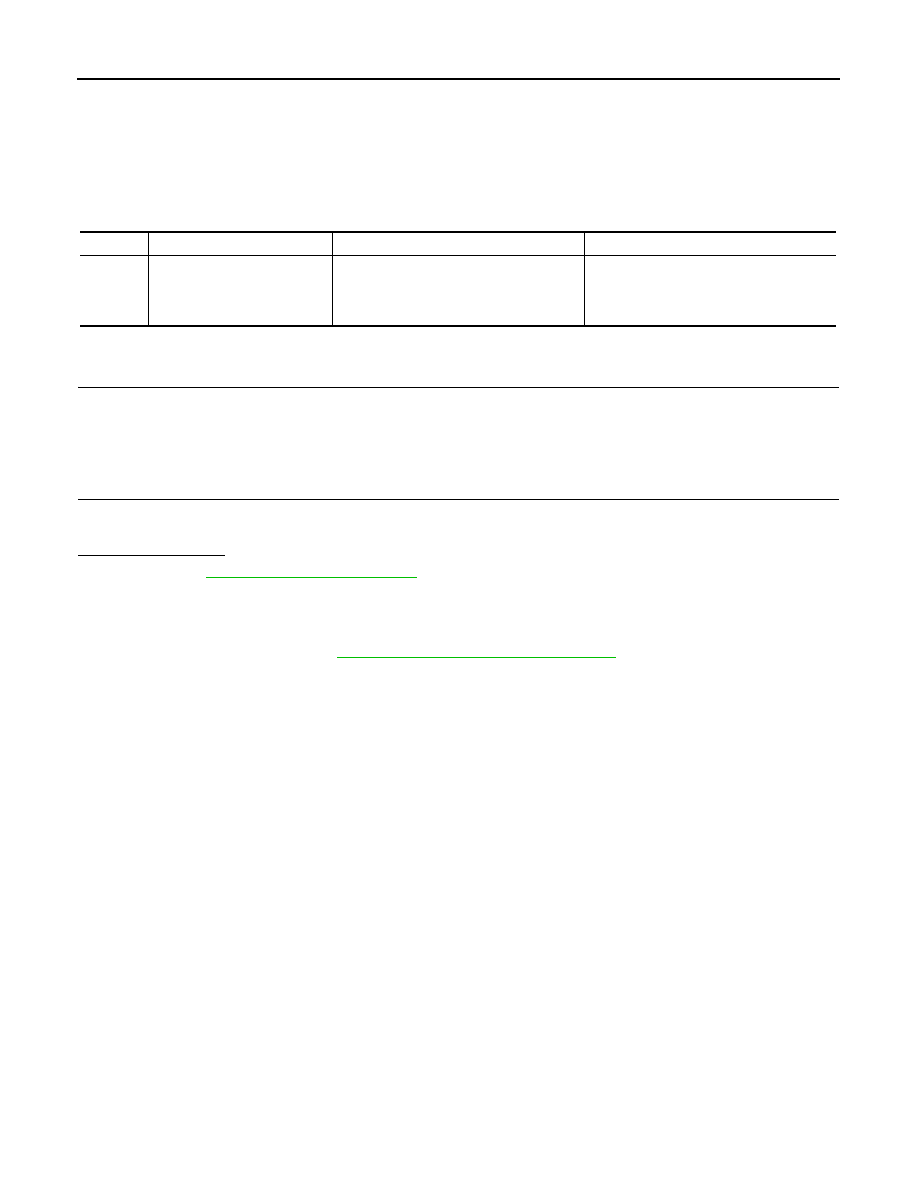
DTC

Trouble diagnosis name

DTC detection condition

Possible causes

U0100

Lost Communication With 
ECM/PCM A 

When the ignition switch is ON, TCM is un-
able to receive the CAN communications 
signal from ECM continuously for 2 sec-
onds or more.

• ECM
• Harness or connector

(CAN communication line is open or 
shorted)

U1000 CAN COMM CIRCUIT

TM-43

< DTC/CIRCUIT DIAGNOSIS >

[CVT: RE0F09B]

C

E

F

G

H

I

J

K

L

M

A

B

TM

N

O

P

U1000 CAN COMM CIRCUIT

Description

INFOID:0000000009719423

CAN (Controller Area Network) is a serial communication line for real time application. It is an on-vehicle mul-
tiplex communication line with high data communication speed and excellent malfunction detection ability.
Many electronic control units are equipped onto a vehicle, and each control unit shares information and links
with other control units during operation (not independent). In CAN communication, control units are con-
nected with 2 communication lines (CAN-H and CAN-L) allowing a high rate of information transmission with
less wiring. Each control unit transmits/receives data but selectively reads required data only.

DTC Logic

INFOID:0000000009719424

DTC DETECTION LOGIC

DTC CONFIRMATION PROCEDURE

NOTE:
Immediately after performing any “DTC CONFIRMATION PROCEDURE”, always turn ignition switch OFF.
Then wait at least 10 seconds before performing the next test.

1.

CHECK DTC DETECTION

With CONSULT

1.

Turn ignition switch ON.

2.

Start engine and wait for at least 6 seconds.

3.

Perform “Self Diagnostic Results” in “TRANSMISSION”.

With GST

Follow the procedure “With CONSULT”.

Is “U1000” detected?

YES

>> Go to 

TM-43, "Diagnosis Procedure"

.

NO

>> Check intermittent incident. Refer to 

GI-44, "Intermittent Incident"

.

Diagnosis Procedure

INFOID:0000000009719425

Go to 

LAN-28, "CAN System Specification Chart"

.

DTC

Trouble diagnosis name

DTC is detected if...

Possible cause

U1000

CAN Communication Line

When TCM is not transmitting or receiving 
CAN communication signal for 2 seconds or 
more.

Harness or connectors
(CAN communication line is open or short-
ed.)

TM-44

< DTC/CIRCUIT DIAGNOSIS >

[CVT: RE0F09B]

U1010 CONTROL UNIT (CAN)

U1010 CONTROL UNIT (CAN)

Description

INFOID:0000000009719426

CAN (Controller Area Network) is a serial communication line for real time application. It is an on-vehicle mul-
tiplex communication line with high data communication speed and excellent malfunction detection ability.
Many electronic control units are equipped onto a vehicle, and each control unit shares information and links
with other control units during operation (not independent). In CAN communication, control units are con-
nected with 2 communication lines (CAN-H and CAN-L) allowing a high rate of information transmission with
less wiring. Each control unit transmits/receives data but selectively reads required data only.

DTC Logic

INFOID:0000000009719427

DTC DETECTION LOGIC

DTC CONFIRMATION PROCEDURE

NOTE:
If “DTC CONFIRMATION PROCEDURE” has been previously performed, always turn ignition switch
OFF and wait at least 10 seconds before performing the next test.
After the repair, perform the following procedure to confirm the malfunction is eliminated.

1.

CHECK DTC DETECTION

With CONSULT

1.

Turn ignition switch ON.

2.

Start engine and wait for at least 6 seconds.

3.

Select “Self Diagnostic Results” in “TRANSMISSION”.

Is “U1010” detected?

YES

>> Go to 

TM-44, "Diagnosis Procedure"

.

NO

>> Check intermittent incident. Refer to 

GI-44, "Intermittent Incident"

.

Diagnosis Procedure

INFOID:0000000009719428

1.

CHECK INTERMITTENT INCIDENT

Refer to 

GI-44, "Intermittent Incident"

.

Is the inspection result normal?

YES

>> Replace the TCM. Refer to 

TM-165, "Exploded View"

.

NO

>> Repair or replace damaged parts.

DTC

Trouble diagnosis name

DTC is detected if...

Possible cause

U1010

TCM Communication Malfunction

When detecting error during the initial diagno-
sis of CAN controller to TCM.

Harness or connectors
(CAN communication line is 
open or shorted.)

P0615 STARTER RELAY

TM-45

< DTC/CIRCUIT DIAGNOSIS >

[CVT: RE0F09B]

C

E

F

G

H

I

J

K

L

M

A

B

TM

N

O

P

P0615 STARTER RELAY

Description

INFOID:0000000009719429

• TCM controls starter relay in IPDM E/R.
• TCM switches starter relay ON at “P” or “N” position and allows to cranking engine. 
• Then it prohibits cranking other than at “P” or “N” position.

DTC Logic

INFOID:0000000009719430

DTC DETECTION LOGIC

DTC CONFIRMATION PROCEDURE

NOTE:
Immediately after performing any “DTC CONFIRMATION PROCEDURE”, always turn ignition switch OFF.
Then wait at least 10 seconds before performing the next test.

1.

CHECK DTC DETECTION

With CONSULT

1.

Turn ignition switch ON.

2.

Perform “Self Diagnostic Results” in “TRANSMISSION”.

Is “P0615” detected?

YES

>> Go to 

TM-45, "Diagnosis Procedure"

.

NO

>> Check intermittent incident. Refer to 

GI-44, "Intermittent Incident"

.

Diagnosis Procedure

INFOID:0000000009719431

1.

CHECK STARTER RELAY SIGNAL

1.

Turn ignition switch OFF.

2.

Disconnect IPDM E/R connector.

3.

Turn ignition switch ON.

4.

Check voltage between IPDM E/R vehicle side harness connector terminal and ground.

Is the inspection result normal?

YES

>> Check starter relay and starter control relay. Refer to 

PCS-10, "Diagnosis Description"

.

NO

>> GO TO 2.

2.

CHECK HARNESS BETWEEN TCM AND IPDM E/R (PART 1)

1.

Turn ignition switch OFF.

2.

Disconnect TCM connector.

3.

Check continuity between TCM vehicle side harness connector terminal and IPDM E/R vehicle side har-
ness connector terminal.

Is the inspection result normal?

DTC

Trouble diagnosis name

DTC is detected if...

Possible cause

P0615

Starter Relay Circuit

If this signal is ON other than in “P” or “N” po-
sition, this is judged to be a malfunction.
(And if it is OFF in “P” or “N” position, this too 
is judged to be a malfunction.)

• Harness or connectors

(Starter relay and TCM circuit is open or 
shorted.)

• Starter relay circuit

IPDM E/R vehicle side harness connector

Ground

Condition

Voltage (Approx.)

Connector

Terminal

F12

72

Selector lever in “P” and “N” positions

Battery voltage

Selector lever in other positions

0 V

TCM vehicle side harness connector

IPDM E/R vehicle side harness connector

Continuity

Connector

Terminal

Connector

Terminal

F23

20

F12

72

Existed


содержание   ..  1373  1374  1375  1376   ..