содержание .. 1359 1360 1361 1362 ..
Nissan Murano. Manual - part 1361
STARTING SYSTEM
STR-7
< SYSTEM DESCRIPTION >
C
D
E
F
G
H
I
J
K
L
M
A
STR
N
P
O
SYSTEM DESCRIPTION
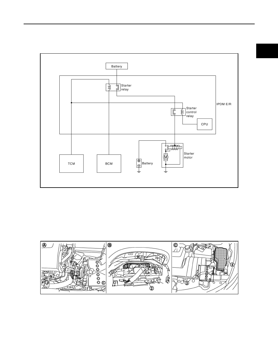
STARTING SYSTEM
System Diagram
INFOID:0000000009722571
System Description
INFOID:0000000009722572
The starter motor plunger closes and provides a closed circuit between the battery and starter motor. The
starter motor is grounded to the engine block. With power and ground supplied, cranking occurs and the
engine starts.
Component Parts Location
INFOID:0000000009722573
JPBIA1665GB
1.
Starter motor
2.
BCM
3.
TCM
4.
IPDM E/R
A.
Cylinder block left side
B.
Behind the combination meter
C.
Engine room dash panel (LH)
JPBIA1756ZZ