содержание .. 1345 1346 1347 1348 ..
Nissan Murano. Manual - part 1347
ST-82
< REMOVAL AND INSTALLATION >
[WITHOUT HEATED STEERING WHEEL]
STEERING COLUMN
STEERING COLUMN
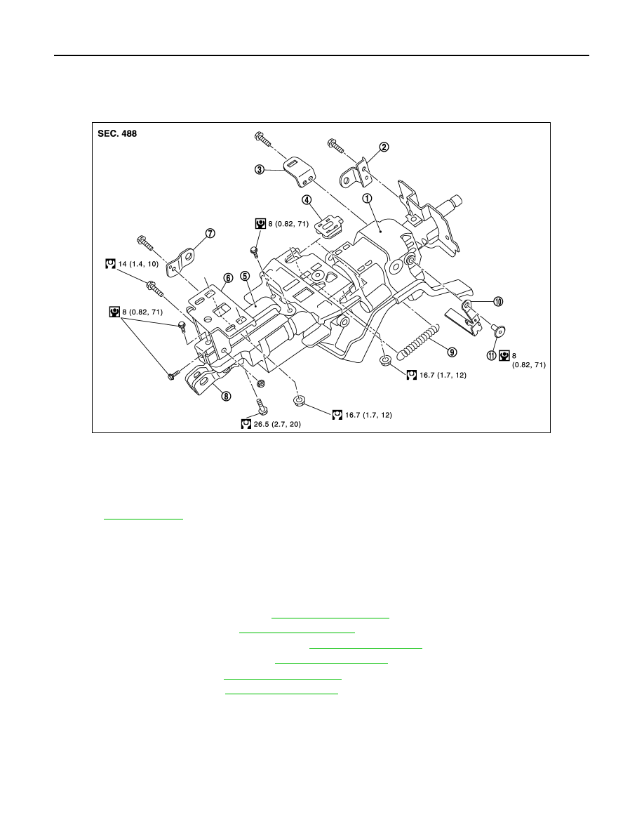
Exploded View
INFOID:0000000009721525
Removal and Installation
INFOID:0000000009721526
REMOVAL
1.
Set the vehicle to the straight-ahead position.
2.
Place the tilt to the highest level. Place the telescopic to the longest level.
3.
Remove driver air bag module. Refer to
.
4.
Remove steering wheel. Refer to
.
5.
Remove instrument driver lower panel. Refer to
.
6.
Remove steering column cover. Refer to
.
7.
Remove spiral cable. Refer to
.
8.
Remove cluster lid A. Refer to
1.
Steering column assembly
2.
Bracket
3.
Bracket
4.
Slide plate
5.
Slide bracket
6.
Lower mount bracket
7.
Bracket
8.
Upper joint
9.
Spring
10. Tilt lever
11.
Clip
Refer to
for symbols in the figure.
JSGIA0610GB