Nissan Murano. Manual - part 131


  Главная      Nissan     Nissan Murano (2014 year) - Service Manual


поиск по сайту            


содержание   ..  129  130  131  132   ..


Nissan Murano. Manual - part 131


AV-302

< PREPARATION >

[BOSE AUDIO WITH NAVIGATION]

PREPARATION

PREPARATION

PREPARATION

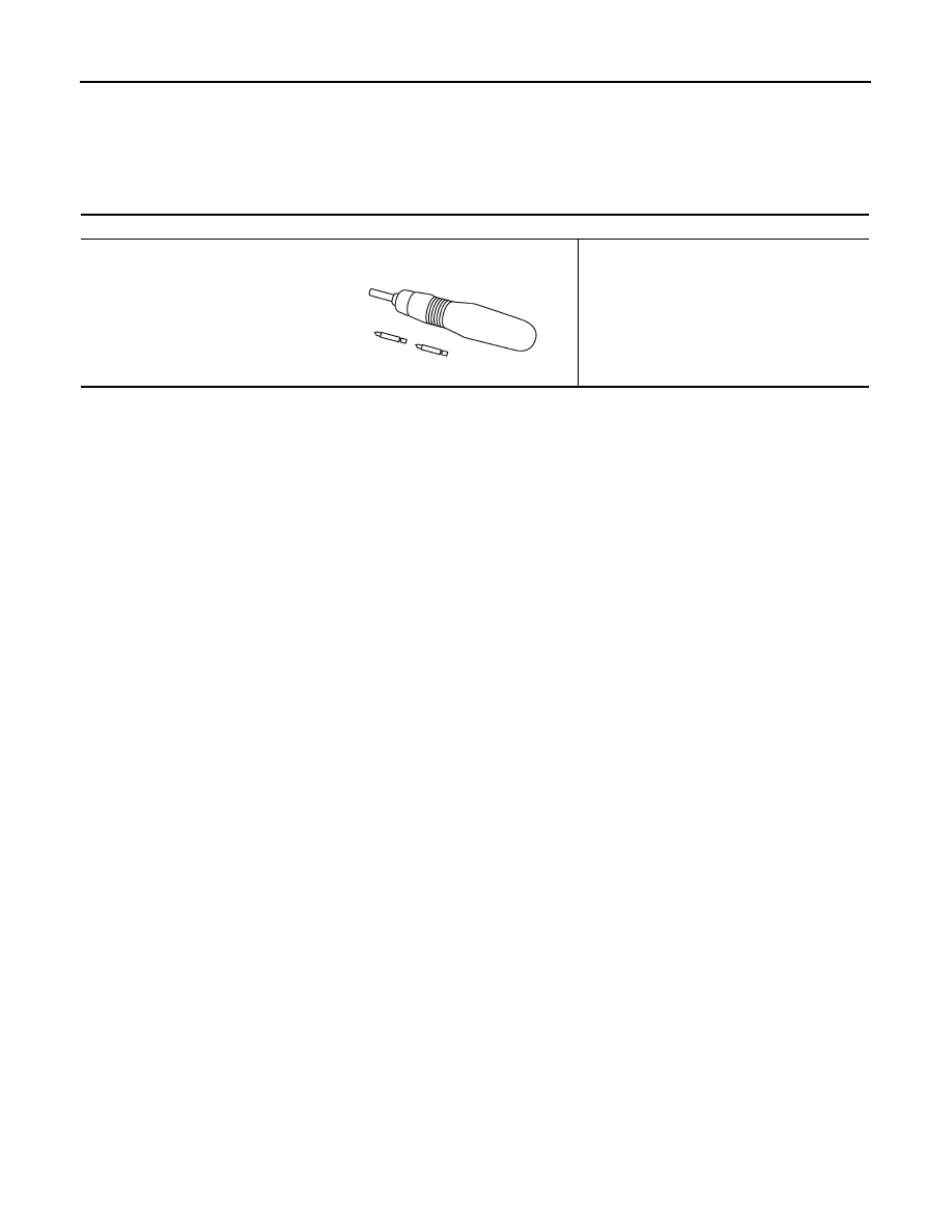
Commercial Service Tools

INFOID:0000000009721842

Tool

Description

Power tool

Loosening screws

PBIC0191E

AV

COMPONENT PARTS

AV-303

< SYSTEM DESCRIPTION >

[BOSE AUDIO WITH NAVIGATION]

C

D

E

F

G

H

I

J

K

L

M

B

A

O

P

SYSTEM DESCRIPTION

COMPONENT PARTS

Component Parts Location

INFOID:0000000009721843

1.

Center speaker

2.

Front squawker LH

3.

Front door speaker LH

4.

Rear door speaker LH

5.

Rear speaker LH

6.

BOSE amp.

7.

Woofer

8.

Rear view camera

9.

Camera control unit (Models with 
LDW and BSW)

10. Rear speaker RH

11.

Antenna base (antenna amp. and 
satellite radio antenna)

12. Rear door speaker RH

13. Front door speaker RH

14. Front squawker RH

15. Microphone

16. GPS antenna

17. Combination meter

18. Steering switch

19. Steering angle sensor

20. Auxiliary input jacks

21. USB connector

22. Preset switch

23. AV control unit

24. Multifunction switch

25. Display unit

JSNIA5572ZZ

AV-304

< SYSTEM DESCRIPTION >

[BOSE AUDIO WITH NAVIGATION]

COMPONENT PARTS

Component Description

INFOID:0000000009721844

A.

Luggage floor center finisher re-
moved condition

B.

Luggage side finisher lower RH is re-
moved condition

C.

Combination meter removed condi-
tion

D.

Spiral cable part

Part name

Description

AV control unit

• Integrates hard disk drive (HDD) allowing map data and music data to be stored. 

(Models with music box)

• Integrates hard disk drive (HDD) allowing map data to be stored. (Models without 

music box)

• It is the master unit of the MULTI AV system, and it is connected to each control 

unit by communication. It operates each system according to communication sig-
nals from the AV control unit.

• The AV control unit includes the audio, rear view monitor, hands-free phone, voice 

control, navigation, USB connection, DVD play, satellite radio and vehicle informa-
tion functions.

• It is connected to ECM and combination meter via CAN communication to obtain 

necessary information for the vehicle information function.

• It is connected to BCM via CAN communication transmitting/receiving for the ve-

hicle settings function.

• It inputs the illumination signals that are required for the display dimming control.
• It inputs the signals for driving status recognition (vehicle speed, reverse and park-

ing brake). 

• The RGB digital image signal and composite image signal are output to display 

unit.

• It supplies power to rear view camera. (Models without LDW and BSW)
• Amp. ON signal and sound signal are transmitted to BOSE amp.
• Update of map data is performed with the DVD-ROM.

Display unit

• Display image is controlled by the serial communication from AV control unit.
• RGB digital image signal is input from AV control unit.
• Composite image signal is input from AV control unit.
• Camera image signal is input from rear view camera. (Models without LDW and 

BSW)

• Camera image signal is input from camera control unit. (Models with LDW and 

BSW)

• Touch panel function can be operated for each system by touching a display di-

rectly.

Camera control unit
(Models with LDW and BSW)

• It supplies power to rear view camera.
• The image of vehicle rear view is transmitted to display unit.
• Controls the LDW and BSW system. Refer to the following.
- LDW system

DAS-12, "System Description"

- BSW system: 

DAS-109, "System Description"

BOSE amp.

Inputs sound signal from AV control unit, and outputs sound signal to each speaker.

Front door speaker

• Outputs sound signal from BOSE amp.
• Outputs sound (mid and low range).

Rear door speaker

• Outputs sound signal from BOSE amp.
• Outputs sound (mid and low range).

Front squawker

• Outputs sound signal from BOSE amp.
• Outputs sound (high and mid range).

Rear speaker

• Outputs sound signal from BOSE amp.
• Outputs sound (high and mid range).

Center speaker

• Outputs sound signal from BOSE amp.
• Outputs sound (high and mid range).

Woofer

• Composed of two woofers.
• Inputs sound signal from BOSE amp.
• Outputs sound (low range).

AV

COMPONENT PARTS

AV-305

< SYSTEM DESCRIPTION >

[BOSE AUDIO WITH NAVIGATION]

C

D

E

F

G

H

I

J

K

L

M

B

A

O

P

*1: Image signals cannot be received from iPod

®

.

Multifunction switch

• Operation panel is equipped with the centralized switch where audio, auxiliary in-

put and navigation, etc. operations are integrated.

• Connected with preset switch via harness, and operation signal is transmitted to 

AV control unit via AV communication. 

Preset switch

• Operation panel is equipped with the centralized switch where audio and air con-

ditioner, etc. operations are integrated.

• Connected with multifunction switch via harness, and operation signal is transmit-

ted to AV control unit via AV communication.

• The disk ejection operating signal is performed by hardwire.

Rear view camera

Models without LDW and BSW

• Camera power supply is input from AV control unit.
• The image of vehicle rear view is transmitted to display unit.

Models with LDW and BSW

• Camera power supply is input from camera control unit.
• The image of vehicle rear view is transmitted to camera control unit.

Steering angle sensor

It is connected to the AV control unit and transmits the steering angle sensor signal 
via CAN communication.

Steering switch

• Operations for audio, hands-free phone, voice control and navigation, etc. are pos-

sible.

• Steering switch signal (operation signal) is output to AV control unit.

Microphone

• Used for hands-free phone function and voice recognition function.
• Microphone signal is transmitted to AV control unit.
• Power (Microphone VCC) is supplied from AV control unit.

Auxiliary input jacks

Image signal and sound signal of auxiliary input are transmitted to AV control unit.

GPS antenna

GPS signal is received and transmitted to AV control unit.

Antenna base

A radio antenna base integrated with radio antenna amp. and satellite radio antenna 
is adopted.

ANTENNA AMP.

• Radio signal received by rod antenna is amplified and transmitted to AV control 

unit.

• Power (antenna amp. ON signal) is supplied from AV control unit.

SATELLITE RADIO ANTENNA

• Receives satellite radio waves and outputs it to AV control unit.

USB connector

Image signal

*1

 and sound signal of USB input is transmitted to AV control unit.

Combination meter (Models with BSW and 
LDW)

Receives buzzer output signal from camera control unit via CAN communication and 
sounds the buzzer.

Part name

Description


содержание   ..  129  130  131  132   ..