содержание .. 126 127 128 129 ..
Nissan Murano. Manual - part 128
AV-290
< REMOVAL AND INSTALLATION >
[BOSE AUDIO WITHOUT NAVIGATION]
REAR VIEW CAMERA
REAR VIEW CAMERA
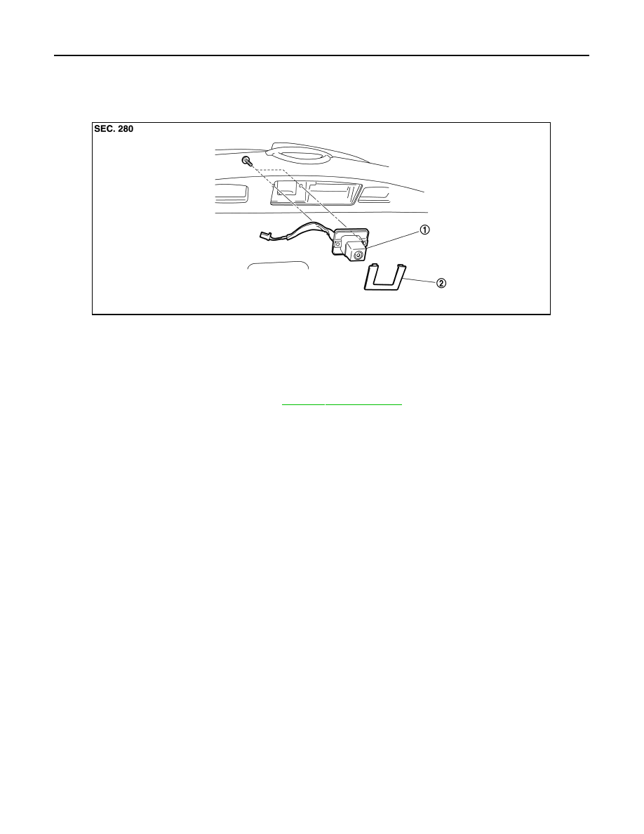
Exploded View
INFOID:0000000009721819
Removal and Installation
INFOID:0000000009721820
REMOVAL
1.
Remove back door finisher inner. Refer to
2.
Remove finisher.
3.
Remove rear view camera screws, disconnect rear view camera connector and remove rear view camera
from back door assembly.
INSTALLATION
Install in the reverse order of removal.
Adjustment
INFOID:0000000009721821
Adjust the guide line position if the guide line position is shifted after installing the rear view camera.
1.
Rear view camera
2.
Finisher
JPNIA0797ZZ