Nissan Murano. Manual - part 1246


  Главная      Nissan     Nissan Murano (2014 year) - Service Manual


поиск по сайту            


содержание   ..  1244  1245  1246  1247   ..


Nissan Murano. Manual - part 1246


B210D STARTER RELAY

SEC-81

< DTC/CIRCUIT DIAGNOSIS >

[WITH INTELLIGENT KEY SYSTEM]

C

D

E

F

G

H

I

J

L

M

A

B

SEC

N

O

P

B210D STARTER RELAY

Description

INFOID:0000000009722807

Located in IPDM E/R, it runs the starter motor. The starter relay is turned ON by the BCM when the ignition
switch is in START position. IPDM E/R transmits the starter relay ON signal to BCM via CAN communication.

DTC Logic

INFOID:0000000009722808

DTC DETECTION LOGIC

NOTE:
• If DTC B210D is displayed with DTC U1000, first perform the trouble diagnosis for DTC U1000. Refer to

SEC-31, "IPDM E/R : DTC Logic"

.

• If DTC B210D is displayed with DTC B2617, first perform the trouble diagnosis for DTC B2617. Refer to

SEC-72, "DTC Logic"

.

DTC CONFIRMATION PROCEDURE

1.

PERFORM DTC CONFIRMATION PROCEDURE

1.

Turn ignition switch ON.

2.

Turn ignition switch OFF and wait for 1 second or more.

3.

Check DTC in “Self Diagnostic Result” mode of “IPDM E/R” using CONSULT.

Is DTC detected?

YES

>> Refer to 

SEC-81, "Diagnosis Procedure"

.

NO

>> INSPECTION END

Diagnosis Procedure

INFOID:0000000009722809

1.

CHECK SELF DIAGNOSTIC RESULT

Check DTC in “Self Diagnostic Result” mode of “IPDM E/R” using CONSULT.
What is the display history of DTC “B210D”?

“CRNT”>> GO TO 2.
“PAST” >> GO TO 4.

2.

CHECK STARTER RELAY CONTROL SIGNAL CIRCUIT VOLTAGE

Check the voltage between IPDM E/R harness connector and ground.

Is the inspection result normal?

YES

>> Replace IPDM E/R. Refer to 

PCS-37, "Removal and Installation"

.

NO

>> GO TO 3.

3.

CHECK STARTER RELAY CONTROL SIGNAL CIRCUIT

1.

Turn ignition switch OFF

2.

Disconnect IPDM E/R connector and BCM connector.

3.

Check continuity between IPDM E/R harness connector and ground.
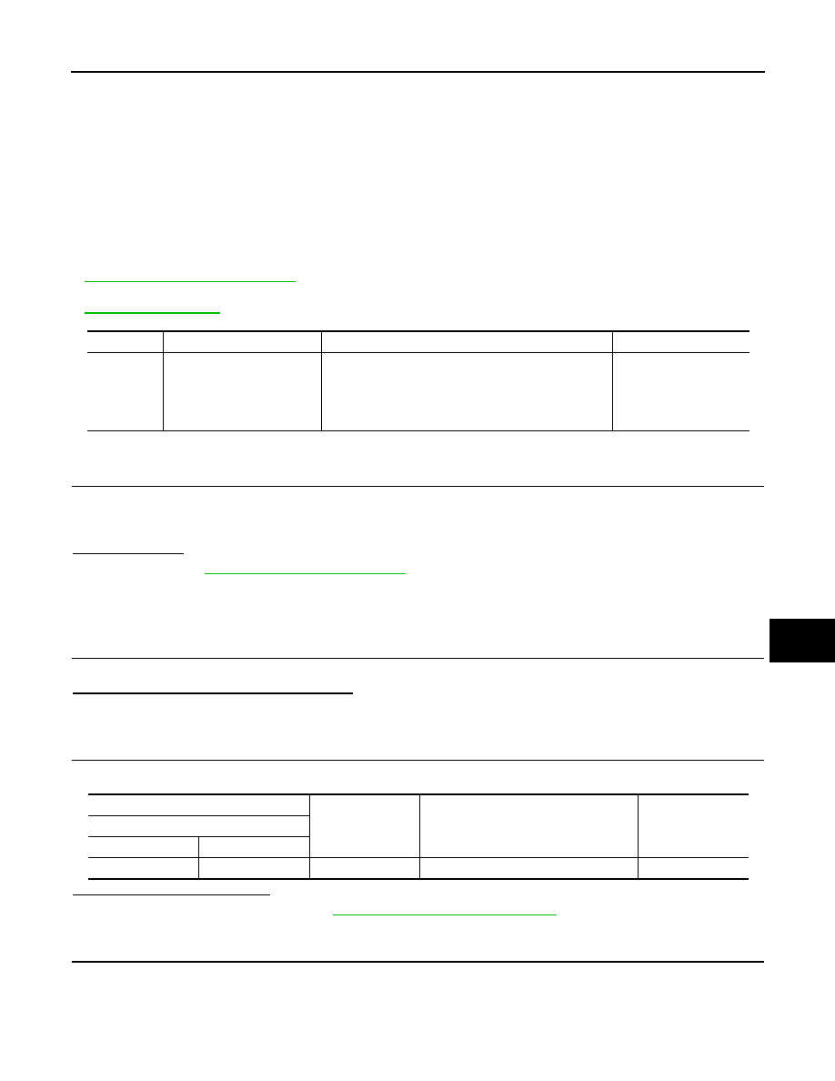
DTC No.

Trouble diagnosis name

DTC detecting condition

Possible cause

B210D

STARTER RLY ON CIRC

IPDM E/R detects that the relay is stuck at ON position 
even if the followings condition are met for about 1 sec-
ond.
• Starter control relay ON/OFF signal from BCM
• Transmission range switch input

IPDM E/R

(+)

(-)

Condition

Voltage

(Approx.)

IPDM E/R

Connector

Terminal

E11

46

Ground

Other than at engine cranking

Battery voltage

SEC-82

< DTC/CIRCUIT DIAGNOSIS >

[WITH INTELLIGENT KEY SYSTEM]

B210D STARTER RELAY

Is the inspection result normal?

YES

>> Perform the diagnosis procedure for DTC B2608 of BCM. Refer to 

SEC-68, "DTC Logic"

.

NO

>> Repair or replace harness.

4.

CHECK INTERMITTENT INCIDENT

Check intermittent incident. Refer to 

GI-44, "Intermittent Incident"

.

>> INSPECTION END

IPDM E/R

Ground

Continuity

Connector

Terminal

E11

46

Not existed

B210E STARTER RELAY

SEC-83

< DTC/CIRCUIT DIAGNOSIS >

[WITH INTELLIGENT KEY SYSTEM]

C

D

E

F

G

H

I

J

L

M

A

B

SEC

N

O

P

B210E STARTER RELAY

Description

INFOID:0000000009722810

Located in IPDM E/R, it runs the starter motor. The starter relay is turned ON by the BCM when the ignition
switch is in START position. IPDM E/R transmits the starter relay ON signal to BCM via CAN communication.

DTC Logic

INFOID:0000000009722811

DTC DETECTION LOGIC

NOTE:
• If DTC B210E is displayed with DTC U1000, first perform the trouble diagnosis for DTC U1000. Refer to

SEC-31, "IPDM E/R : DTC Logic"

.

• If DTC B210E is displayed with DTC B2110 for IPDM E/R, first perform the trouble diagnosis for DTC B2110.

Refer to 

SEC-87, "DTC Logic"

.

• If DTC B210E is displayed with DTC B2617 for BCM, first perform the trouble diagnosis for DTC B2617.

Refer to 

SEC-72, "DTC Logic"

.

• When IPDM E/R power supply voltage is low (Approx. 7 - 8 V for about 1 second), the DTC B210F may be

detected.

DTC CONFIRMATION PROCEDURE

1.

PERFORM DTC CONFIRMATION PROCEDURE

1.

Press push-button ignition switch to start engine, and wait 1 seconds or more.

2.

Check DTC in “Self Diagnostic Result” mode of “IPDM E/R” using CONSULT.

Is DTC detected?

YES

>> Refer to 

SEC-83, "Diagnosis Procedure"

.

NO

>> INSPECTION END

Diagnosis Procedure

INFOID:0000000009722812

1.

CHECK SELF DIAGNOSTIC RESULT

Check DTC in “Self Diagnostic Result” mode of “IPDM E/R” using CONSULT.

What is the display history of DTC “B210E”?

“CRNT”>> GO TO 3.
“PAST” >> GO TO 2.

2.

CHECK BATTERY VOLTAGE

Check the battery voltage.

Which is the measurement result?

More than 12.4 V>>GO TO 5.
Less than 12.4 V>>Perform battery inspection. Refer to 

PG-3, "How to Handle Battery"

.

3.

CHECK STARTER RELAY CONTROL SIGNAL

Check voltage between IPDM E/R harness connector and ground.

Is the inspection result normal?

DTC No.

Trouble diagnosis name

DTC detecting condition

Possible cause

B210E

STARTER RLY OFF CIRC

IPDM E/R detects that the relay is stuck at OFF position even if the 
followings condition are met for about 1 second.
• Starter control relay ON/OFF signal from BCM
• Transmission range switch input

• IPDM E/R
• Battery

(+)

(-)

Condition

Voltage

(Approx.)

IPDM E/R

Connector

Terminal

E11

46

Ground

Other than at engine cranking

Battery voltage

SEC-84

< DTC/CIRCUIT DIAGNOSIS >

[WITH INTELLIGENT KEY SYSTEM]

B210E STARTER RELAY

YES

>> GO TO 4.

NO

>> Replace IPDM E/R. Refer to 

PCS-37, "Removal and Installation"

.

4.

CHECK STARTER RELAY CONTROL SIGNAL CIRCUIT

1.

Turn ignition switch OFF.

2.

Disconnect BCM connector and IPDM E/R connector.

3.

Check continuity between BCM harness connector and IPDM E/R harness connector.

Is the inspection result normal?

YES

>> Replace BCM. Refer to 

BCS-98, "Removal and Installation"

.

NO

>> Repair or replace harness.

5.

CHECK INTERMITTENT INCIDENT

Check intermittent incident. Refer to 

GI-44, "Intermittent Incident"

.

>> INSPECTION END

BCM

IPDM E/R

Continuity

Connector

Terminal

Connector

Terminal

M121

52

E11

46

Existed


содержание   ..  1244  1245  1246  1247   ..