Nissan Murano. Manual - part 1036


  Главная      Nissan     Nissan Murano (2014 year) - Service Manual


поиск по сайту            


содержание   ..  1034  1035  1036  1037   ..


Nissan Murano. Manual - part 1036


MWI-24

< SYSTEM DESCRIPTION >

METER SYSTEM

WARNING LAMPS/INDICATOR LAMPS : Component Description

INFOID:0000000009721251

METER ILLUMINATION CONTROL

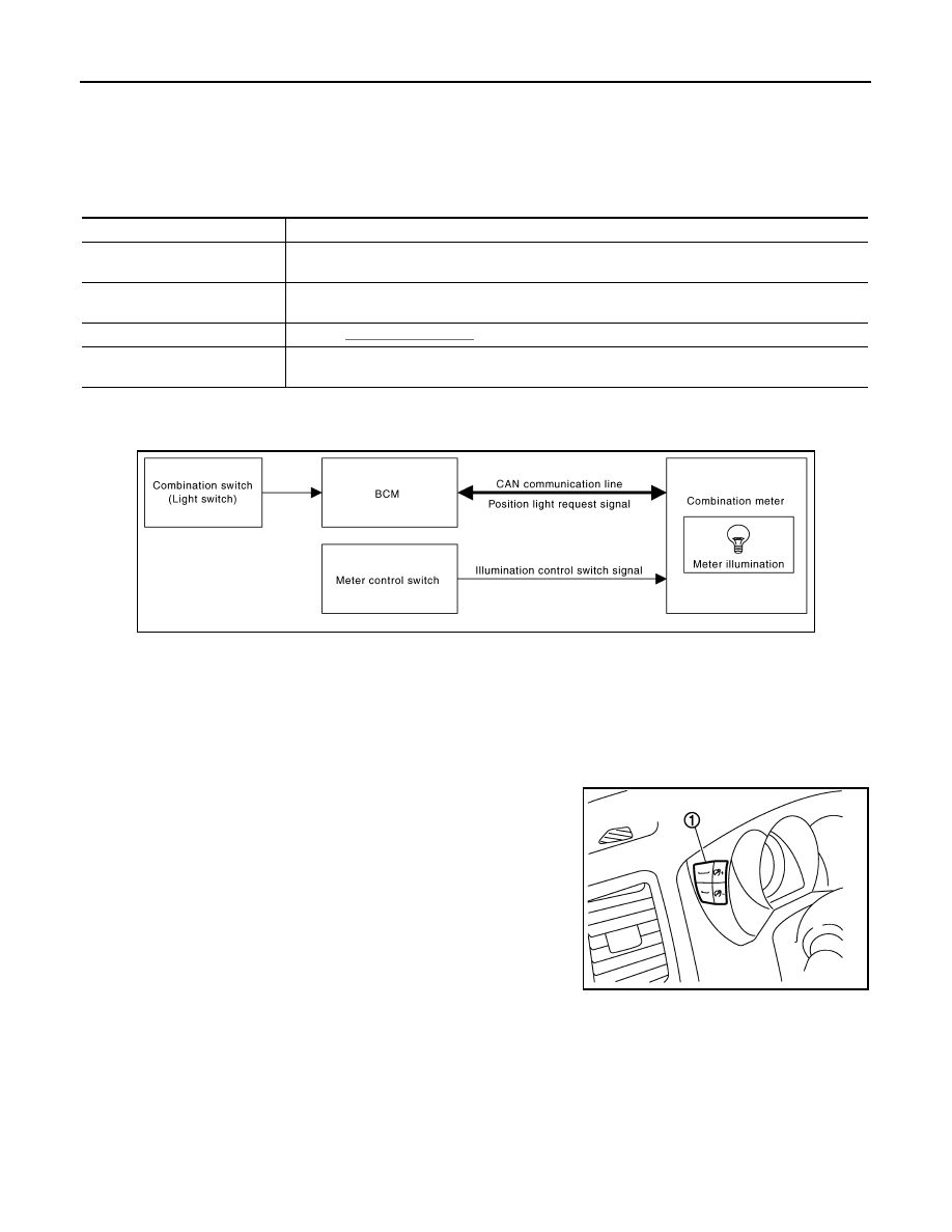
METER ILLUMINATION CONTROL : System Diagram

INFOID:0000000009721252

METER ILLUMINATION CONTROL : System Description

INFOID:0000000009721253

SYSTEM DESCRIPTION

The combination meter controls the meter illumination by the illumination control switch signal from the meter
control switch and the position light request signal transmitted by the BCM via CAN communication.

Daytime Mode

Meter illumination level can be adjusted in 22 steps using the illumi-
nation control switch (1) in daytime mode.

Nighttime Mode

• Combination meter changes the meter illumination to the nighttime mode by the position light request signal

from BCM via CAN communication.

• Meter illumination can be adjusted in 22 steps using the illumination control switch in nighttime mode.

Driver Welcome Function

Ring illumination gradually turns ON when a driver gets in the vehicle with intelligent key and closes the driver
side door.
NOTE:
Ring illumination gradually turns OFF when not turning the ignition switch ON at a certain period of time.

A.

Lower right side of rear seat

B.

Engine room (RH)

C.

Engine front side

D.

Engine room (LH)

E.

Front bumper (left back)

F.

Engine room (LH)

G.

Engine room (LH)

H.

Behind the combination meter

I.

Lower left side of rear seat

Unit

Description

Combination meter

Turns the oil pressure warning lamp ON/OFF according to the oil pressure switch signal received 
from BCM via CAN communication. 

IPDM E/R

Reads the ON/OFF signals from the oil pressure switch and transmits the oil pressure switch signal 
to the combination meter via BCM and CAN communication. 

Oil pressure switch

Refer to 

MWI-52, "Description"

BCM

Transmits the oil pressure switch signal received from IPDM E/R via CAN communication to the 
combination meter via CAN communication. 

JPNIA0746GB

JPNIA0742ZZ

MWI

METER SYSTEM

MWI-25

< SYSTEM DESCRIPTION >

C

D

E

F

G

H

I

J

K

L

M

B

A

O

P

Dial Effects Function

Combination meter detects the engine start when input engine speed signal at first. Pointers of speed meter
and tachometer sweep and ring illumination gradually turns ON when combination meter detects the engine
start. Then, combination meter starts the normal control.
NOTE:
• Engine coolant temperature gauge and fuel gauge do not function.
• Dial Effects Function can be turned ON/OFF from “SETTING” on the information display.

METER ILLUMINATION CONTROL : Component Parts Location

INFOID:0000000009721254

JPNIA0813ZZ

MWI-26

< SYSTEM DESCRIPTION >

METER SYSTEM

METER ILLUMINATION CONTROL : Component Description

INFOID:0000000009721255

INFORMATION DISPLAY

INFORMATION DISPLAY : System Diagram

INFOID:0000000009721256

INFORMATION DISPLAY : System Description

INFOID:0000000009721257

DESCRIPTION

1.

Fuel level sensor unit (sub)

2.

ABS actuator and electric unit (con-
trol unit)

3.

Oil pressure switch

4.

TCM

5.

Ambient sensor

6.

ECM

7.

IPDM E/R

8.

BCM

9.

Combination meter

10.

Fuel level sensor unit and fuel pump 
(main)

A.

Lower right side of rear seat

B.

Engine room (RH)

C.

Engine front side

D.

Engine room (LH)

E.

Front bumper (left back)

F.

Engine room (LH)

G.

Engine room (LH)

H.

Behind the combination meter

I.

Lower left side of rear seat

Unit

Description

Combination meter

Controls the meter illumination with the illumination control switch signal from the meter control 
switch and the position light request signal from BCM via CAN communication.

BCM

Transmits the position light request signal to the combination meter via CAN communication.

Meter control switch

Transmits the following signals to the combination meter.

• Illumination control switch signal (+)

• Illumination control switch signal (–)

JPNIA0747GB

MWI

METER SYSTEM

MWI-27

< SYSTEM DESCRIPTION >

C

D

E

F

G

H

I

J

K

L

M

B

A

O

P

• The combination meter receives the information required for controlling the operations of the information dis-

play from the BCM via CAN communication.

• The combination meter incorporates a trip computer that displays the warning / information according to the

information received from various units.

PARKING BRAKE RELEASE WARNING

The combination meter indicates the parking brake release warning judged by the vehicle speed signal
received from the ABS actuator and electric unit (control unit) via CAN communication and the parking brake
switch signal from the parking brake switch.

Warning Operation Condition

Parking brake release warning is judged if all of the following conditions are fulfilled.
• Vehicle speed is 7 km/h (4.3 MPH) or higher
• Parking brake switch ON

LOW FUEL WARNING

The combination meter indicates the low fuel warning judged by the fuel level sensor signal received from the
fuel level sensor unit.

Warning Operation Condition

• Fuel level: Approx. 9.8   (2-5/8 US gal, 2-1/8 Imp gal) or less

LOW WASHER FLUID WARNING

The combination meter indicates the low washer fluid warning judged by the signal from the washer level
switch.

Warning Operation Condition

• Indicates the warning when the washer level switch is ON for 180 seconds or more. Stops indicating the

warning when the washer level switch is OFF for 30 seconds or more.

LOW TIRE PRESSURE WARNING

• The combination meter receives remaining low tire pressure warning lamp signal from the BCM with CAN

communication line.

• The combination meter indicates low tire pressure warning when receiving remaining low tire pressure warn-

ing lamp signal.

• The combination meter indicates low tire pressure warning judged with the low tire pressure warning lamp

signal received from the BCM.

For details, refer to 

WT-8, "System Description"

.

FUEL FILLER CAP WARNING

• The combination meter receives remaining fuel filler cap warning display signal from the ECM with CAN

communication line.

• The combination meter indicates fuel filler cap warning when receiving remaining fuel filler cap warning dis-

play signal.

• The combination meter indicates fuel filler cap warning judged with the fuel filler cap warning display signal

received from the ECM.

For details, refer to 

EC-108, "System Description"

.

DOOR OPEN WARNING

• The combination meter indicates the door open warning judged by each door switch signal received from the

BCM via CAN communication line.

INSTANTANEOUS FUEL CONSUMPTION

JSNIA0033GB


содержание   ..  1034  1035  1036  1037   ..