Nissan Murano. Manual - part 1035


  Главная      Nissan     Nissan Murano (2014 year) - Service Manual


поиск по сайту            


содержание   ..  1033  1034  1035  1036   ..


Nissan Murano. Manual - part 1035


MWI-20

< SYSTEM DESCRIPTION >

METER SYSTEM

ODO/TRIP METER : Component Description

INFOID:0000000009721243

SHIFT POSITION INDICATOR

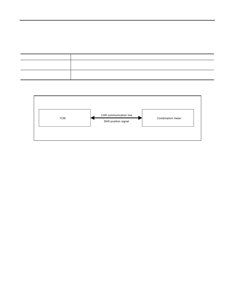
SHIFT POSITION INDICATOR : System Diagram

INFOID:0000000009721244

SHIFT POSITION INDICATOR : System Description

INFOID:0000000009721245

• Shift position is displayed in the shift position indicator in the combination meter.
• TCM transmits the shift position signal to the combination meter via CAN communication.
• The combination meter indicates shift position according to the shift position signal received via CAN com-

munication.

A.

Lower right side of rear seat

B.

Engine room (RH)

C.

Engine front side

D.

Engine room (LH)

E.

Front bumper (left back)

F.

Engine room (LH)

G.

Engine room (LH)

H.

Behind the combination meter

I.

Lower left side of rear seat

Unit

Description

Combination meter

Converts the vehicle speed signal received from the ABS actuator and electric unit (control unit) via 
CAN communication to mileage, and it displays the accumulated mileage to the odo/trip meter. 

ABS actuator and electric unit
(control unit)

Transmits the vehicle speed signal to the combination meter via CAN communication. 

JPNIA0745GB

MWI

METER SYSTEM

MWI-21

< SYSTEM DESCRIPTION >

C

D

E

F

G

H

I

J

K

L

M

B

A

O

P

SHIFT POSITION INDICATOR : Component Parts Location

INFOID:0000000009721246

JPNIA0813ZZ

1.

Fuel level sensor unit (sub)

2.

ABS actuator and electric unit (con-
trol unit)

3.

Oil pressure switch

4.

TCM

5.

Ambient sensor

6.

ECM

7.

IPDM E/R

8.

BCM

9.

Combination meter

10.

Fuel level sensor unit and fuel pump 
(main)

MWI-22

< SYSTEM DESCRIPTION >

METER SYSTEM

SHIFT POSITION INDICATOR : Component Description

INFOID:0000000009721247

WARNING LAMPS/INDICATOR LAMPS

WARNING LAMPS/INDICATOR LAMPS : System Diagram

INFOID:0000000009721248

WARNING LAMPS/INDICATOR LAMPS : System Description

INFOID:0000000009721249

OIL PRESSURE WARNING LAMP

• IPDM E/R reads the ON/OFF signals from the oil pressure switch and transmits the oil pressure switch sig-

nal to the combination meter via BCM with the CAN communication line. 

• The combination meter turns the oil pressure warning lamp ON/OFF according to the oil pressure switch sig-

nal received via CAN communication. 

A.

Lower right side of rear seat

B.

Engine room (RH)

C.

Engine front side

D.

Engine room (LH)

E.

Front bumper (left back)

F.

Engine room (LH)

G.

Engine room (LH)

H.

Behind the combination meter

I.

Lower left side of rear seat

Unit

Description

Combination meter

Displays the shift position on the shift position indicator with shift position signal received from TCM 
via CAN communication.

TCM

Transmits shift position signal to the combination meter with CAN communication.

JSNIA0449GB

MWI

METER SYSTEM

MWI-23

< SYSTEM DESCRIPTION >

C

D

E

F

G

H

I

J

K

L

M

B

A

O

P

WARNING LAMPS/INDICATOR LAMPS : Component Parts Location

INFOID:0000000009721250

JPNIA0813ZZ

1.

Fuel level sensor unit (sub)

2.

ABS actuator and electric unit (con-
trol unit)

3.

Oil pressure switch

4.

TCM

5.

Ambient sensor

6.

ECM

7.

IPDM E/R

8.

BCM

9.

Combination meter

10.

Fuel level sensor unit and fuel pump 
(main)


содержание   ..  1033  1034  1035  1036   ..