содержание .. 99 100 101 102 ..
Nissan Murano. Manual - part 101
AV-182
< SYSTEM DESCRIPTION >
[BOSE AUDIO WITHOUT NAVIGATION]
DIAGNOSIS SYSTEM (AV CONTROL UNIT)
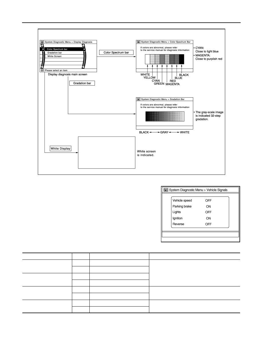
Display Diagnosis
Vehicle Signals
A comparison check can be made of each actual vehicle signal and
the signals recognized by the system.
JSNIA2233GB
JSNIA0149GB
Diagnosis item
Display
Vehicle status
Remarks
Vehicle speed
ON
Vehicle speed > 0 km/h (0 MPH)
Changes in indication may be delayed. This is normal.
OFF
Vehicle speed = 0 km/h (0 MPH)
Parking brake
ON
Parking brake is applied.
OFF
Parking brake is released.
Lights
ON
Lighting switch is ON
—
OFF
Lighting switch is OFF
Ignition
ON
Ignition switch is ON
—
OFF
Ignition switch is in ACC position