содержание .. 100 101 102 103 ..
Nissan Murano. Manual - part 102
AV-186
< SYSTEM DESCRIPTION >
[BOSE AUDIO WITHOUT NAVIGATION]
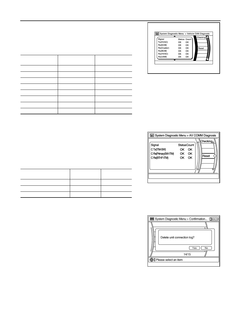
DIAGNOSIS SYSTEM (AV CONTROL UNIT)
• CAN communication status and error counter is displayed.
• The error counter displays “OK” if any malfunction was not
detected in the past and displays “0” if a malfunction is detected. It
increases by 1 if the condition is normal at the next ignition switch
ON cycle. The upper limit of the counter is 39.
• The error counter is erased if “Reset” is pressed.
NOTE:
“???” indicates UNKWN.
AV COMM Diagnosis
• Displays the communication status between AV control unit (mas-
ter unit) and each unit.
• The error counter displays “OK” if any malfunction was not
detected in the past and displays “0” if a malfunction is detected. It
increases by 1 if the condition is normal at the next ignition switch
ON cycle. The upper limit of the counter is 39.
• The error counter is erased if “Reset” is pressed.
NOTE:
“???” indicates UNKWN.
Delete Unit Connection Log
Deletes any unit connection records and error records from the AV
control unit memory. (Clear the records of the unit that has been
removed.)
Initialize Settings
Items
Display (Current)
Malfunction counter
(Past)
Tx(HVAC)
OK / ???
OK / 0 – 39
Rx(ECM)
OK / ???
OK / 0 – 39
Rx(Cluster)
OK / ???
OK / 0 – 39
Rx(BCM)
OK / ???
OK / 0 – 39
Rx(HVAC)
OK / ???
OK / 0 – 39
Rx(USM)
OK / ???
OK / 0 – 39
Rx(VDC)
OK / ???
OK / 0 – 39
Rx(STRG)
OK / ???
OK / 0 – 39
JSNIA2235ZZ
Items
Status
(Current)
Counter
(Past)
C Tx(ITM-PrimarySW)
OK / ???
OK / 0 – 39
C Rx(PrimarySW-ITM)
OK / ???
OK / 0 – 39
C Rx(BTHF-ITM)
OK / ???
OK / 0 – 39
JSNIA2505ZZ
JSNIA0088GB