Nissan Murano. Manual - part 98


  Главная      Nissan     Nissan Murano (2014 year) - Service Manual


поиск по сайту            


содержание   ..  96  97  98  99   ..


Nissan Murano. Manual - part 98


AV-170

< PRECAUTION >

[BOSE AUDIO WITHOUT NAVIGATION]

PRECAUTIONS

• When using air or electric power tools or hammers, always switch the ignition OFF, disconnect the

battery, and wait at least 3 minutes before performing any service.

FOR MEXICO : Precautions for Removing of Battery Terminal

INFOID:0000000010137955

•  When removing the 12V battery terminal, turn OFF the ignition

switch and wait at least 30 seconds.
NOTE:
ECU may be active for several tens of seconds after the ignition
switch is turned OFF. If the battery terminal is removed before ECU
stops, then a DTC detection error or ECU data corruption may
occur.

•  For vehicles with the 2-batteries, be sure to connect the main bat-

tery and the sub battery before turning ON the ignition switch.
NOTE:
If the ignition switch is turned ON with any one of the terminals of
main battery and sub battery disconnected, then DTC may be
detected.

•  After installing the 12V battery, always check "Self Diagnosis Result" of all ECUs and erase DTC.

NOTE:
The removal of 12V battery may cause a DTC detection error.

FOR MEXICO : Precaution for Trouble Diagnosis

INFOID:0000000009721712

AV COMMUNICATION SYSTEM

• Do not apply voltage of 7.0 V or higher to the measurement terminals.
• Use the tester with its open terminal voltage being 7.0 V or less.
• Be sure to turn ignition switch OFF and disconnect the battery cable from the negative terminal before

checking the circuit.

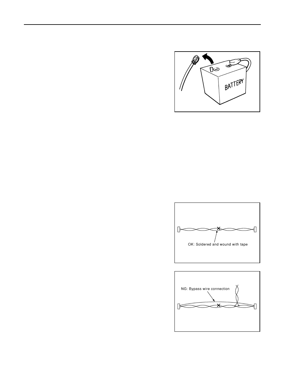
FOR MEXICO : Precaution for Harness Repair

INFOID:0000000009721713

AV COMMUNICATION SYSTEM

• Solder the repaired parts, and wrap with tape. [Frays of twisted line

must be within 110 mm (4.33 in).]

• Do not perform bypass wire connections for the repair parts. (The

spliced wire will become separated and the characteristics of
twisted line will be lost.)

SEF289H

PKIA0306E

PKIA0307E

AV

PREPARATION

AV-171

< PREPARATION >

[BOSE AUDIO WITHOUT NAVIGATION]

C

D

E

F

G

H

I

J

K

L

M

B

A

O

P

PREPARATION

PREPARATION

Commercial Service Tools

INFOID:0000000009721714

Tool

Description

Power tool

Loosening screws

PBIC0191E

AV-172

< SYSTEM DESCRIPTION >

[BOSE AUDIO WITHOUT NAVIGATION]

COMPONENT PARTS

SYSTEM DESCRIPTION

COMPONENT PARTS

Component Parts Location

INFOID:0000000009721715

1.

Center speaker

2.

Front squawker LH

3.

Front door speaker LH

4.

Rear door speaker LH

5.

Rear speaker LH

6.

Satellite radio tuner

7.

TEL adapter unit

8.

BOSE amp.

9.

Woofer

10. Rear view camera

11. TEL antenna

12. Rear speaker RH

13.

Antenna base (antenna amp. and sat-
ellite radio antenna)

14. Rear door speaker RH

15. Front door speaker RH

16. Front squawker RH

17. Microphone

18. Steering angle sensor

19. Steering switch

20. USB connector

21. Auxiliary input jacks

22. Preset switch

23. AV control unit

24. Multifunction switch

25. Display unit

A.

Luggage floor finisher is removed con-
dition

B.

Luggage floor finisher is removed con-
dition

C.

Spiral cable part

JSNIA3507ZZ

AV

COMPONENT PARTS

AV-173

< SYSTEM DESCRIPTION >

[BOSE AUDIO WITHOUT NAVIGATION]

C

D

E

F

G

H

I

J

K

L

M

B

A

O

P

Component Description

INFOID:0000000009721716

Part name

Description

AV control unit

• It is the master unit of the MULTI AV system, and it is connected to each control 

unit by communication. It operates each system according to communication 
signals from the AV control unit.

• The AV control unit includes the audio, rear view monitor, USB connection and 

vehicle information functions.

• It is connected to ECM and combination meter via CAN communication to obtain 

necessary information for the vehicle information function.

• It is connected to BCM via CAN communication transmitting/receiving for the ve-

hicle settings function.

• It inputs the illumination signals that are required for the display dimming control.
• It inputs the signals for driving status recognition (vehicle speed, reverse and 

parking brake). 

• It supplies power to the rear camera.
• Amp. ON signal and sound signal are transmitted to BOSE amp.
• TEL voice signal is input from TEL adapter unit.

Display unit

• Display image is controlled by the serial communication from AV control unit.
• It receives the power (signal VCC and inverter VCC) from the AV control unit and 

operates.

• RGB image signal is input from AV control unit (RGB, RGB area and RGB syn-

chronizing).

• Composite image signals (auxiliary input and camera images) are input from AV 

control unit.

• Synchronizing signal (HP, VP) is output to AV control unit.

BOSE amp.

Inputs sound signal from AV control unit, and outputs sound signal to each speak-
er.

Front door speaker

• Outputs sound signal from BOSE amp.
• Outputs sound (mid and low range).

Rear door speaker

• Outputs sound signal from BOSE amp.
• Outputs sound (mid and low range).

Front squawker

• Outputs sound signal from BOSE amp.
• Outputs sound (high and mid range).

Rear speaker

• Outputs sound signal from BOSE amp.
• Outputs sound (high and mid range).

Center speaker

• Outputs sound signal from BOSE amp.
• Outputs sound (high and mid range).

Woofer

• Composed of two woofers.
• Inputs sound signal from BOSE amp.
• Outputs sound (low range).

Multifunction switch

• Operation panel is equipped with the centralized switch where audio and auxil-

iary input, etc. operations are integrated.

• Connected with preset switch via harness, and operation signal is transmitted to 

AV control unit via AV communication. 

Preset switch

• Operation panel is equipped with the centralized switch where audio and air 

conditioner, etc. operations are integrated.

• Connected with multifunction switch via harness, and operation signal is trans-

mitted to AV control unit via AV communication.

• The disk ejection operating signal is performed by hardwire.

Rear view camera

• Camera power supply is input from AV control unit.
• The image of vehicle rear view is transmitted to AV control unit.

Steering angle sensor

It is connected to the AV control unit and transmits the steering angle sensor signal 
via CAN communication.

Steering switch

• Operations for audio and hands-free phone are possible.
• Steering switch signal (operation signal) is output to AV control unit.


содержание   ..  96  97  98  99   ..