содержание .. 94 95 96 97 ..
Nissan Murano. Manual - part 96
AV-162
< REMOVAL AND INSTALLATION >
[BASE AUDIO WITH COLOR DISPLAY]
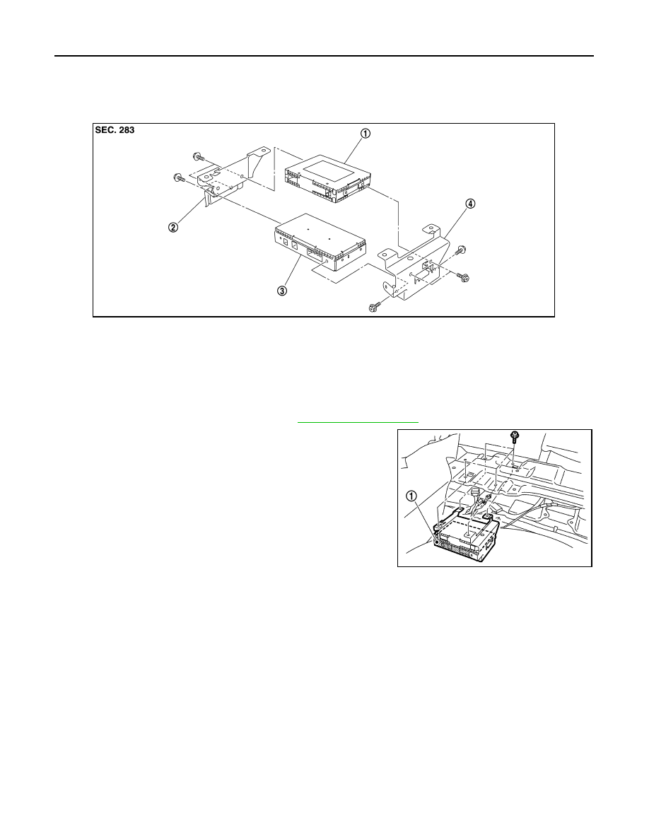
TEL ADAPTER UNIT
TEL ADAPTER UNIT
Exploded View
INFOID:0000000009721696
Removal and Installation
INFOID:0000000009721697
REMOVAL
1.
Remove luggage floor finisher front. Refer to
2.
Remove TEL adapter unit (1) with satellite radio tuner as a sin-
gle unit from the vehicle.
3.
Remove bracket screws, and them remove TEL adapter unit.
INSTALLATION
Install in the reverse order of removal.
1.
Satellite radio tuner
2.
Bracket LH
3.
TEL adapter unit
4.
Bracket RH
JPNIA0784ZZ
JPNIA0805ZZ