содержание .. 88 89 90 91 ..
Nissan Murano. Manual - part 90
AV-138
< DTC/CIRCUIT DIAGNOSIS >
[BASE AUDIO WITH COLOR DISPLAY]
STEERING SWITCH SIGNAL B CIRCUIT
STEERING SWITCH SIGNAL B CIRCUIT
Description
INFOID:0000000009721665
Transmits the steering switch signal to AV control unit.
Diagnosis Procedure
INFOID:0000000009721666
1.
CHECK STEERING SWITCH SIGNAL B CIRCUIT
1.
Turn ignition switch OFF.
2.
Disconnect AV control unit connector and spiral cable connector.
3.
Check continuity between AV control unit harness connector and spiral cable harness connector.
4.
Check continuity between AV control unit harness connector and ground.
Is the inspection result normal?
YES
>> GO TO 2.
NO
>> Repair harness or connector.
2.
CHECK SPIRAL CABLE
Check spiral cable.
Is the inspection result normal?
YES
>> GO TO 3.
NO
>> Replace spiral cable. Refer to
(except for Mexico) or
(for Mexico).
3.
CHECK AV CONTROL UNIT VOLTAGE
1.
Connect AV control unit connector and spiral cable connector.
2.
Turn ignition switch ON.
3.
Check voltage between AV control unit harness connector.
Is the inspection result normal?
YES
>> GO TO 4.
NO
>> Replace AV control unit. Refer to
4.
CHECK STEERING SWITCH
1.
Turn ignition switch OFF.
2.
Check steering switch. Refer to
AV-139, "Component Inspection"
Is the inspection result normal?
YES
>> INSPECTION END
NO
>> Replace steering switch. Refer to
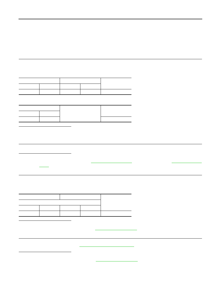
AV control unit
Spiral cable
Continuity
Connector
Terminal
Connector
Terminal
M171
16
M33
31
Existed
AV control unit
Ground
Continuity
Connector
Terminal
M171
16
Not existed
(+)
(
−
)
Voltage
(Approx.)
AV control unit
Connector
Terminal
Connector
Terminal
M171
16
M171
15
3.3 V