Nissan Murano. Manual - part 91


  Главная      Nissan     Nissan Murano (2014 year) - Service Manual


поиск по сайту            


содержание   ..  89  90  91  92   ..


Nissan Murano. Manual - part 91


AV-142

< SYMPTOM DIAGNOSIS >

[BASE AUDIO WITH COLOR DISPLAY]

MULTI AV SYSTEM SYMPTOMS

SYMPTOM DIAGNOSIS

MULTI AV SYSTEM SYMPTOMS

Symptom Table

INFOID:0000000009721671

OPERATION

RELATED TO HANDS-FREE PHONE

• Before performing diagnosis, confirm that the cellular phone being used by the customer is compatible with

the vehicle.

• It is possible that a malfunction is occurring due to a version change of the phone even though the phone is

a compatible type. This can be confirmed by changing the cellular phone to another compatible type, and
checking that it operates normally. It is important to determine whether the cause of the malfunction is the
vehicle or the cellular phone.

Check Compatibility

1.

Make sure the customer's Bluetooth

®

 related concern is understood.

2.

Verify the customer's concern.
NOTE:
The customer's phone may be required, depending upon their concern.

3.

Write down the customer's phone brand, model, and service provider.
NOTE:
It is necessary to know the service provider. On occasion, a given phone may be on the approved list with
one provider, but may not be on the approved list with other providers.

4.

Go to “www.nissanusa.com/bluetooth/”.

a.

Using the website's search engine, find out if the customer's phone is on the approved list.

b.

If the customer's phone is NOT on the approved list:
Stop diagnosis here. The customer needs to obtain a Bluetooth

®

 phone that is on the approved list before

any further action.

c.

If the feature related to the customer's concern shows as “N” (not compatible):
Stop diagnosis here. If the customer still wants the feature to function, they will need to get an approved
phone showing the feature as “Y” (compatible) in the “Basic Features” list.

d.

If the feature related to the customer's concern shows as “Y” (compatible):
Perform diagnosis as per the following table.
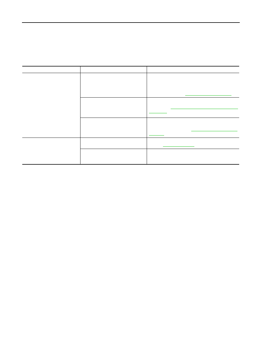
Symptoms

Check items

Probable malfunction location

Multifunction switch and preset 
switch operation does not work.

• All switches cannot be operated.
• “MULTI AV” is displayed on system 

selection screen when the CONSULT 
is started.

• Multifunction switch power supply and ground circuit.
• AV communication circuit between AV control unit and 

multifunction switch.
Perform “Self Diagnostic Result” of “MULTI AV” with 
CONSULT. Refer to 

AV-65, "CONSULT Function"

.

• All switches cannot be operated.
• “MULTI AV” is not displayed on sys-

tem selection screen when the CON-
SULT is initialized.

AV control unit power supply and ground circuit malfunc-
tion. Refer to 

AV-118, "AV CONTROL UNIT : Diagnosis 

Procedure"

.

Only specified switch cannot be operat-
ed.

Multifunction switch or preset switch malfunction.
Perform multifunction switch and preset switch self-di-
agnosis function. Refer to 

AV-56, "On Board Diagnosis 

Function"

.

Fuel economy display is abnor-
mal.

There is malfunction in the CONSULT 
“self-diagnosis result” of “MULTI AV”.

Perform detected DTC diagnosis.
Refer to 

AV-77, "DTC Index"

.

There is no malfunction in the CON-
SULT “self-diagnosis result” of “MULTI 
AV”.

Ignition signal circuit malfunction. (AV control unit)

AV

MULTI AV SYSTEM SYMPTOMS

AV-143

< SYMPTOM DIAGNOSIS >

[BASE AUDIO WITH COLOR DISPLAY]

C

D

E

F

G

H

I

J

K

L

M

B

A

O

P

RELATED TO CAMERA

RELATED TO RGB IMAGE

Symptoms

Check items

Probable malfunction location

Does not recognize cellular 
phone connection. (No con-
nection is displayed on the dis-
play at the guide.)

Repeat the registration of cellular phone.

TEL adapter unit malfunction.
Refer to 

AV-162, "Removal and Installation"

.

Hands-free phone cannot be 
established.

Both the reception and the speech cannot 
be performed

• Perform “Self Diagnostic Result” of “MULTI AV” with 

CONSULT.
Refer to 

AV-65, "CONSULT Function"

.

• No malfunction.

TEL adapter unit malfunction.
Refer to 

AV-162, "Removal and Installation"

.

• Malfunction is detected. 

Perform detected DTC diagnosis.
Refer to 

AV-77, "DTC Index"

.

The other party's voice cannot 
be heard by hands-free phone.

Steering switch's “


” switch works.

TEL voice signal circuit malfunction between TEL adapt-
er unit and AV control unit.

Steering switch's “


” switch do not 

work.

Control signal circuit malfunction.
Refer to 

AV-135, "Diagnosis Procedure"

.

Originating sound is not heard 
by the other party with hands-
free phone communication.

Sound operation function is normal.

TEL adapter unit malfunction.
 Refer to 

AV-162, "Removal and Installation"

.

Sound operation function does not work.

Microphone signal circuit malfunction.
Refer to 

AV-133, "Diagnosis Procedure"

.

The system cannot be operat-
ed.

Steering switch's “SOURCE”, “MENU 
UP”, and “MENU DOWN” switches works, 

but “


” it does not work.

Steering switch malfunction.
Replace steering switch. Refer to 

AV-156, "Exploded 

View"

.

Steering switch's “SOURCE”, “MENU 

UP”, “MENU DOWN” and “


” switch-

es do not work.

Steering switch signal B circuit malfunction.
Refer to 

AV-138, "Diagnosis Procedure"

.

All steering switches do not work.

Steering switch ground circuit malfunction.
Refer to 

AV-140, "Diagnosis Procedure"

.

Symptoms

Check items

Probable malfunction location

Camera image is not shown.
(Vehicle width and predictive 
course line is displayed.)

AUX image is displayed.

Camera image signal circuit.
Refer to 

AV-130, "Diagnosis Procedure"

.

AUX image is not displayed.

Composite image signal circuit.
Refer to 

AV-128, "Diagnosis Procedure"

.

Camera image is not shown.
(displayed in black and nothing 
can be displayed)

• Horizontal synchronizing (HP) signal circuit malfunc-

tion between AV control unit and display unit. Refer to 

AV-126, "Diagnosis Procedure"

.

• Vertical synchronizing (VP) signal circuit malfunction 

between AV control unit and display unit. Refer to 

AV-

127, "Diagnosis Procedure"

.

Camera image does not switch.

“Reverse” is not turned ON on “Vehicle 
Signals” screen of “Confirmation/Adjust-
ment”.

Reverse signal circuit malfunction.

“Reverse” is turned ON on “Vehicle Sig-
nals”screen of “Confirmation/Adjustment”.

AV control unit malfunction.
Replace AV control unit. Refer to 

AV-149, "Exploded 

View"

.

AV-144

< SYMPTOM DIAGNOSIS >

[BASE AUDIO WITH COLOR DISPLAY]

MULTI AV SYSTEM SYMPTOMS

RELATED TO AUDIO

Symptoms

Check items

Possible malfunction location / Action to take

RGB image is not shown.

There is malfunction in the CONSULT 
“self-diagnosis result” of “MULTI AV”.

Perform detected DTC diagnosis.
Refer to 

AV-77, "DTC Index"

.

There is no malfunction in CONSULT 
“self-diagnosis results” of “MULTI AV”.

Vertical synchronizing (VP) signal circuit.
Refer to 

AV-127, "Diagnosis Procedure"

.

Color of RGB image is not 
proper.

Light blue (Cyan) tint.

RGB signal (R: red) circuit.
Refer to 

AV-121, "Diagnosis Procedure"

.

Purple (Magenta) tint.

RGB signal (G: green) circuit.
Refer to 

AV-122, "Diagnosis Procedure"

.

Screen looks yellowish.

RGB signal (B: blue) circuit.
Refer to 

AV-123, "Diagnosis Procedure"

.

RGB screen is rolling.

RGB synchronizing signal circuit.
Refer to 

AV-124, "Diagnosis Procedure"

.

Fuel economy display is mal-
functioning.

There is malfunction in the CONSULT 
“self-diagnosis result” of “MULTI AV”.

Perform detected DTC diagnosis.
Refer to 

AV-77, "DTC Index"

.

There is no malfunction in CONSULT 
“self-diagnosis results” of “MULTI AV”.

Ignition signal circuit malfunction. (AV control unit)

Symptoms

Check items

Probable malfunction location

The disk cannot be removed.

Disk eject signal circuit malfunction.
Refer to 

AV-132, "Diagnosis Procedure"

.

No sound comes out or the lev-
el of the sound is low.

No sound from all speakers.

AV control unit power supply and ground circuits malfunc-
tion. Refer to 

AV-118, "AV CONTROL UNIT : Diagnosis 

Procedure"

.

Only a certain speaker (front right, front 
left, rear right, or rear left, etc.) does not 
output sound.

• Poor connector connection of speaker.
• Sound signal circuit malfunction between AV control 

unit and speaker.

• Malfunction in speaker.
• Malfunction in AV control unit.

Noise is mixed with audio. 

Noise comes out from all speakers.

Malfunction in AV control unit.

Noise comes out only from a certain 
speaker (front right, front left, rear right, 
or rear left, etc.).

• Poor connector connection of speaker.
• Sound signal circuit malfunction between AV control 

unit and speaker.

• Malfunction in speaker.
• Poor installation of speaker (e.g. backlash and loose-

ness)

• Malfunction in AV control unit.

Noise is mixed with radio only (when the 
car hits a bump or while driving over bad 
roads).

• Poor connector connection of antenna or antenna feed-

er.

• Loose antenna base mounting nut. Refer to 

AV-165, 

"Exploded View"

.

Radio is not received or poor 
reception.

• Other audio sounds are normal.
• Any radio cannot be received or poor 

reception is caused even after moving 
to a service area with good reception 
(e.g. a place with clear view and no ob-
stacles generating external noises). 

• Antenna amp. ON signal circuit malfunction.
• Poor connector connection of antenna or antenna feed-

er. 

• Loose antenna base mounting nut. Refer to 

AV-165, 

"Exploded View"

.

AV

MULTI AV SYSTEM SYMPTOMS

AV-145

< SYMPTOM DIAGNOSIS >

[BASE AUDIO WITH COLOR DISPLAY]

C

D

E

F

G

H

I

J

K

L

M

B

A

O

P

RELATED TO USB

NOTE:
Check that there is no malfunction of USB equipment main body before performing a diagnosis.

iPod

®

 is a trademark of Apple inc., registered in the U.S. and other countries.

RELATED TO STEERING SWITCH

RELATED TO AUXILIARY INPUT

NOTE:
Check that there is no malfunction of AUX equipment main body before performing a diagnosis.

Satellite radio is not received.

There is malfunction in the CONSULT 
self-diagnosis result.
Refer to 

AV-65, "CONSULT Function"

.

• Malfunction in antenna, antenna feeder, or AV control 

unit. Perform DTC diagnosis. Refer to 

AV-77, "DTC In-

dex"

.

• Poor continuity in antenna feeder. 
• Poor connector connection of antenna or antenna feed-

er.

There is no malfunction in the CONSULT 
self-diagnosis result.
Refer to 

AV-65, "CONSULT Function"

.

• Poor continuity in antenna feeder. 
• Poor connector connection of antenna or antenna feed-

er.

• Loose satellite radio antenna mounting nut.

Refer to 

AV-165, "Exploded View"

.

Symptoms

Check items

Probable malfunction location

Symptoms

Check items

Possible malfunction location / Action to take

iPod

®

 or USB memory can not 

be recognized.

• USB harness malfunction.
• USB connector malfunction.

Symptoms

Probable malfunction location

None of the steering switch operations work.

Steering switch ground circuit malfunction.
Refer to 

AV-140, "Diagnosis Procedure"

.

Only specified switch cannot be operated.

Steering switch malfunction.
Replace steering switch. Refer to 

AV-156, "Exploded View"

.

“SOURCE”, “MENU UP”, “MENU DOWN”, “


” switches 

are not operated.

Steering switch signal A circuit.
Refer to 

AV-136, "Diagnosis Procedure"

.

”VOL UP“, “VOL DOWN”, “

” switches are not operated.

Steering switch signal B circuit.
Refer to 

AV-138, "Diagnosis Procedure"

.

Symptoms

Check items

Probable malfunction location

No voice sound is heard when 
AUX mode is selected.

Voice sound is heard when other modes 
are selected.

AUX sound signal circuit.

Image is not displayed when 
AUX mode is selected.

Camera image is displayed.

AUX image signal circuit malfunction.
Refer to 

AV-129, "Diagnosis Procedure"

.

Camera image is not displayed.

Composite image signal circuit malfunction.
Refer to 

AV-128, "Diagnosis Procedure"

.


содержание   ..  89  90  91  92   ..